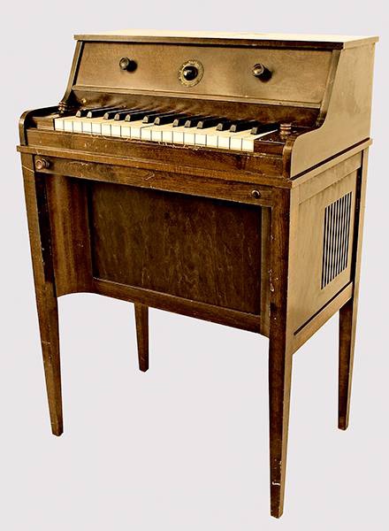
The Emicon at the National Music Museum (Vermillion, South Dakota, USA)
The Emicon (Model S) – the name derived from that of the distributors, M.I. Conn in New York – was designed in Budapest, Hungary by electronics engineer Nicholas Langer and Hungarian instrument designer, John Halmágyi and later manufactured in the USA. The Emicon was a monophonic 32 note keyboard controlled instrument based on the same type of heterodyning vacuum tube oscillator technology first used in the Thereminvox a decade earlier. Langer designed the instrument to be able to create more complex tones than the standard vacuum tube sine wave and therefore used a single neon gas-discharge tubes to produce a type of sawtooth wave with richer harmonics; “In general, pure sinusoidal oscillations, when converted into sound, are not satisfactory from the musical point of view as they impress us as empty and meaningless” – Langer’s Emicon was said to be able to produce tones similar to a cello, saxophone, oboe, trumpet, mandolin, guitar and bagpipe and was said to be the instrument that inspired Harald Bode to start designing electronic musical instruments. Designed as a portable domestic instrument, The Emicon was housed in a shallow rectangular case small enough to sit on a tabletop and could be attached directly to a domestic radio receiver, public address system, amplifier, or any similar equipment. 1 Davies, Hugh,(2014) The Emicon, Electronic valve Instruments, Grove Online, 08 December 2014.
“Charles D. Stein shows a model how to play the Emicon at the Texas Centennial Exposition in Dallas in June 1936.”Langer’s patent for the Emicon
The Emicon was manufactured and marketed by Emicon, Inc., Deep River, Connecticut, CA from 1932. A later portable travelling model was built into case with an amplifier in separate case similar to later instruments such as the Ondioline. A single example of the Emicon survives at the Charles D. Stein Collection of Early Electronic Instruments at the National Music Museum, Vermilion, South Dakota, USA. Langer moved from Hungary to the USA sometime in 1932 and continued to develop improved versions of the Emicon and filed numerous patents for electronic musical instruments until the 1950s.
The Rangertone Organ was a large electronic tone-wheel based organ developed by the electronics engineer and pioneer of audio recording Richard Ranger in the 1930’s. The instrument was marketed by Ranger from his own company ‘Rangertone Incorporated’ on Verona Ave. in Newark, NJ. Very few of the instruments were sold, one of which was installed at the Recital hall of Skinner Hall of Music, Vassar College. After the failure to sell the instrument Ranger went on to develop a series of high fidelity phonograph devices that never went into production. During WW2 Ranger spent time investigating German electronic equipment for the US Army and it was here that he picked up and removed for his own use the German AEG Magnetophone tape recorder. Ranger returned to the U.S. and in 1947 announced his new Rangertone Tape recorder, based on the Magnetophone, which finally gave the Rangertone Inc the financial success it needed until squeezed out of the domestic market by larger companies such as Ampex.
Richard Ranger with the wireless facsimile system. in 1924, Richard Ranger invented the wireless photoradiogram, or transoceanic radio facsimile, the forerunner of today’s fax machines. A photograph of President Calvin Coolidge sent from New York to London in November 1924 became the first photo picture reproduced by transoceanic radio facsimile.
The Rangertone Organ was one of the early tone wheel organs, similar to the Hammond Organ and much earlier Telharmonium (1906). Uniquely, the Rangertone Organ had its pitch stability controlled by tuning forks, therefore it was possible to change the temperament by changing the tuning of the forks. Timbre was controlled by push-buttons to the right of the keyboard, and/or by switching between six different amplifier/speaker combinations, which had different tremolo and tonal qualities.The original version was a huge machine, with more than 150 valves. A portable single-keyboard model was built for concert performance.1
Ranger made the first public demonstration of his huge ‘pipeless organ’ at Newark, New Jersey in 1931:
Interior of the Rangertone organ. Image: Proceedings of the institute of Radio Engineers November 1936 Volume 24, Number 11, 1444.
“Ranger’s apparatus consisted essentially of twelve separate sets of motor-driven alternators precisely maintained at given rotational speeds, by tuning-fork control apparatus. One of these sets of alternators, as shown in Fig. 5, generated all the required C’s; another all the C sharps; another the D’s, and so forth. From these alternators he obtained all the desired fundamentals and their true harmonic frequencies for the tempered scale. Timbre control switches selected the partials and their amplitudes for any desired tone quality. Amplifiers were, of course, used with reproducers to translate the feeble audio currents into sound.
Ranger’s improvements over the basic work of Cahill were made possible by the advent of the vacuum tube. For example, he provides means for automatic selection of different amplifiers, for different simultaneously produced tones, to prevent cross modulation in a single amplifier; means for avoiding keying transients, for accentuating high or low frequencies, for restricting tremolo to specific components of a complex tone, and at different tremolo rates, means to provide glissando effects, for regulating the temperament, for providing damped wave trains in simulation of percussive tones, and numerous other details.” 1 Meissner, Benjamin. F,(1936) Electronic music and instruments, Proceedings of the institute of Radio Engineers November 1936 Volume 24, Number 11, 1444.
Ranger, Richard Howard – Inventor, USA *13.06.1889-10.01.1962+ with the Rangertone Organ 1930 – Image: Sennecke Vintage property of ullstein bild (Photo by Robert Sennecke/ullstein bild via Getty Images)
Interior of the Rangertone organ. Image: Proceedings of the institute of Radio Engineers November 1936 Volume 24, Number 11, 1444.
“Ranger’s apparatus consisted essentially of twelve separate sets of motor-driven alternators precisely maintained at given rotational speeds, by tuning-fork control apparatus. One of these sets of alternators, as shown in Fig. 5, generated all the required C’s; another all the C sharps; another the D’s, and so forth. From these alternators he obtained all the desired fundamentals and their true harmonic frequencies for the tempered scale. Timbre control switches selected the partials and their amplitudes for any desired tone quality. Amplifiers were, of course, used with reproducers to translate the feeble audio currents into sound.
Ranger’s improvements over the basic work of Cahill were made possible by the advent of the vacuum tube. For example, he provides means for automatic selection of different amplifiers, for different simultaneously produced tones, to prevent cross modulation in a single amplifier; means for avoiding keying transients, for accentuating high or low frequencies, for restricting tremolo to specific components of a complex tone, and at different tremolo rates, means to provide glissando effects, for regulating the temperament, for providing damped wave trains in simulation of percussive tones, and numerous other details.” 1 Meissner, Benjamin. F,(1936) Electronic music and instruments, Proceedings of the institute of Radio Engineers November 1936 Volume 24, Number 11, 1444. ↩︎
Ivan Eremeeff holding a 9 inch sheet of sixty optical tones from the Syntronic Organ. Image: Popular Mechanics, January 1936,20-2.
The Syntronic Organ
In the early 1930s the world-renowned conductor and at the time the director of the Philadelphia Symphony Orchestra, Leopold Stokowski began to search for ways of augmenting or even replacing a conventional orchestra with amplified and electronic instruments. Stokowski, who had premiered many of Edgard Varese’s works in the 1920s and championed Varese’s experiments with electronic sound, added a Theremin Cello to the Philadelphia Orchestra to reinforce the double bass parts of the score – later replacing this with a specially adapted Ondes Martenot.1 Davies, Hugh, (2014) Electronic Musical Instruments, The Grove dictionary of musical instruments, New York : Oxford University Press,168.
Eremeeff’s diagram of a networked orchestra of 20 Syntronic Organs. Image: US Patent 1,924,713, June 4, 1932.
Ivan Eremeeff began a collaboration with Stokowski around 1932 with the aim of creating an all-electronic orchestra equipped with thirty five connected electronic instruments designed by Eremeeff:
“plans are being discussed with a view to a symphony orchestra which is composed exclusively of electronic organs, of which there will be about 35. The instruments are designed to be portable and compact, and will utilize the synthetic wave films as described, for the production of various types of music, such as produced by ordinary well-known musical instruments as the violin, the flute, the piccolo, etc. , and also music the timbre or tone of which has not been heard before.”
An artists depiction of Stokowski’s synchronised orchestra with multiple connected Syntronic Organs. Image: Popular Mechanics, January 1936, 20-2.
“The symphony orchestra of the future will not be a band of a hundred or more musicians, carrying a carload of instruments, but a small group of fifteen or twenty men, each carrying a small roll of film. This small group will be able to play symphonies and other selections with greater precision, and better effects, than could be obtained from an orchestra made up of hundreds of artists playing the finest musical instruments. In fact, they will be able to obtain effects that cannot even be approximated with actual musical instruments, since every instrument has its physical limitations.
The impulses from these various devices go to a ‘mixing board,’ where they are “mixed” and enter the loud-speakers. man at the mixing board controls the volume of the various instruments. With this arrangement, the conductor will not stand before the orchestra, but a motion picture will be taken of the orchestra leader con-ducting. The picture will be shown on a screen, and the operators of the devices will follow his leading on the screen.
The conductor himself will sit at the control panels situated in the audience. He will be able to regulate the speed at which the film run, and also regulate the sound. The conductor thus, at his ease, will get the same effect as the audience. The music itself will come from loud-speakers situated about the auditorium instead of emanating from the stage on which the musicians appear.”2 Music of the Future now a Reality, Popular Mechanics, January 1936, 20-2.
Syntronic Organ circa 1933
The Syntronic project was based at the new WCAU building in Philadelphia and sponsored by the radio station’s president Dr Leon levy. The first product of this collaboration was the Syntronic Organ unveiled at WCAU in 1934. 3 Kassell, Edward, E, (1934) A “Syntronic” Organ, Radio Craft, August 1934, 77,104-6. The Syntronic Organ was designed specifically for a networked orchestra of interconnected electronic instruments – i.e. ‘Synchronised – Electronic’ or, as Eremeeff described it in his 1932 patent:
“a system consisting of one or more synchronously coupled electrical musical instruments, each of which is capable of producing electrically tones of predetermined pitch, predetermined synthetic quality, and predetermined tonal expressions, the latter being produced by various keying means, with provision, if desired, for tremolo and a continuing diminishing of the tones after the keying has been discontinued.”4Eremeeff, Ivan, (1932), SYNTHETIC ELECTRICAL MUSICAL SYSTEM. US Patent 1,924,713, filed June 4, 1932 .
The dual keyboards of the Syntronic Organ. Image: Popular Mechanics, January 1936, 20-2.
The Syntronic Organ was a photo-electric type instrument controlled by two manual keyboards each controlling its own sound producing unit and it was designed, not just to reproduce the sound of a pipe organ, but be able to electronically recreate all the instruments of the orchestra and numerous new sound effects. Thomas Rhea described in detail the technical operation of the instrument in The Art of Electronic Music:
“This instrument is yet another of the type that has a stationary illuminated mask governing tone colour. However, Eremeeff departed from the typical tone-wheel design. Instead he used a film with transparent “light slits” which passed rapidly over the photoelectric cell. Some models had a “pitch film” that would run for a limited time — just like a tape recorder. Another version had an endless-loop pitch film. The following is a synopsis of the operating principles of the Syntronic Organ (please refer to the diagram fig1.):
The rapidly moving pitch film (a) rode on padded rollers, driven by a variable-speed motor that allowed tuning. The quality mask (b ) was divided into sections and could be advanced manually (c ) or by motor (d) to provide a selection of tone colours. Light from sources (e ) was projected through the selected quality mask, then through variable “translucency disks” (f,g) which provided pedal control of volume and speed of tremolo. Finally the light passed through the running pitch film (a) onto a photo- electric cell. When a given key was depressed, an associated light shutter (h) was raised. This allowed the light to pass through the quality mask and fall on a single pitch track of the film. (The instrument was completely polyphonic, having 88 such shutters. ) The light shutters rode in the spacers of the “diminishing rollers” (i). which revolved at a controllable speed in the direction which would cause the light shutters to return to their original position (creating silence ). The Syntronic Organ’s envelope (loudness ) control was remarkable. Each light shutter had a spring that held it against the diminishing rollers. A pedal could be used to simultaneously alter the speed of these rollers, and control the volume using the translucency disk (i) permitting the tones to fade away. That is, the Syntronic Organ could hold the sound and create a gradual release after the fingers left the keyboard — like a synthesizer. When spring tension was released, the shutters were freed: then when a key was depressed, its associated shutter would drop by its own weight back to its resting place. This created short tones comparable to staccato tones on a piano —or “zero sustain” on a synthesizer envelope generator that controls the voltage-controlled amplifier. Also. the 88-note keyboard was scaled so that “… each frequency of the musical scale has its own predetermined intensity.” Eremeeff designed not only this fascinating instrument, but the entire technology necessary for its support. He constructed a “universal” recorder capable of creating pitch and quality films by exposing running film to light patterns generated by a “flicker box.” The pitch films were composed of numerous repeating uniform slits or apertures produced by rotating cams of the appropriate shape; light was permitted to pass through their openings and expose the film, creating tracks of definite frequency. To prepare quality films (masks ), the recorder used cams with predetermined wave patterns cut into their peripheries, these too, revolved in the path of the light beams projected onto the running raw film. Naturally, the quality tracks were produced in a size that would correctly correspond to the associated pitch track.“5 Rhea, Thomas, L,(1984) Photo-Electric Instruments, The Art of Electronic Music – GPI Publications, 13.
Stokowski’s ambitious plans for an all electronic orchestra ultimately never came to fruition because of disagreements between Stokowski and the orchestra’s management. Stokowski re-visited the plan with a mixed 150 acoustic and 24 electronic instrument orchestra for San Francisco 1939 Golden gate Exhibition – a plan that similarly failed to materialise. it seems that Stokowski’s disagreements with the Philadelphia Symphony orchestra’s management board and his frustration at being unable to realise his musical-technical vision lead to his eventual retirement from the orchestra in 1941.6 Davies, Hugh, (2014) Electronic Musical Instruments, The Grove dictionary of musical instruments, New York : Oxford University Press,168.
The WCAU Photona
The Photona at WCAU Philadelphia played by Leonard ‘Melody-Mac’ MacClain in 1935. Image: Theatre organ, 1962.
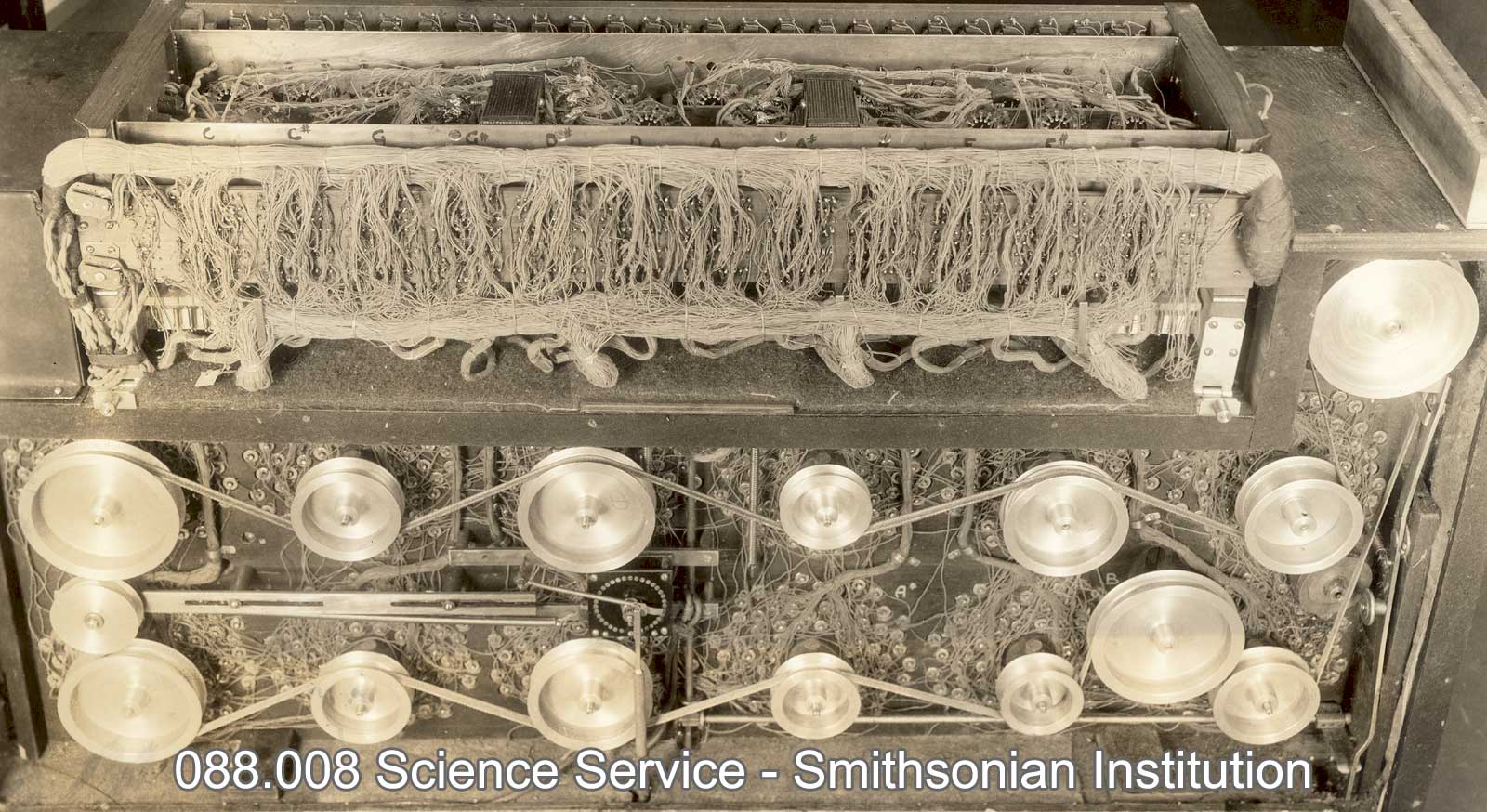
Ivan Eremeef later created the Photona , a cut-down commercial version of the Syntronic Organ. This instrument followed the same photo-electrical system as the Syntronic Organ and was developed by Eremeeff with the John Leitch at the engineering department of WCAU broadcasting station in Philadelphia, USA. The Photonahad twelve rotating optical discs illuminated by nine hundred six volt lamps. The instrument was played with two six octave manual keyboards and two foot pedals for volume and tremolo. The instrument its official debut on February 10, 1935, according to nation-wide press reports, and was officially presented to the public over coast-to-coast radio broadcasts and abroad, for 6 months, beginning on April 6, 1935. An article in the Theatre Organ describes the launch of the Photona:
“Leonard MacClain played the first electronic organ over a coast to coast broadcast on April 6, 193 5. It was the newly invented Photona, built by Ivan Eremeeff, on the photo-electric cell principle. Asked what he thought of it, Mac re plied, “It be longs in an institute!” And that is where it is today – the Franklin Institute. It has no pedals, and was very noisy, with the speaker placed in another room to get away from the racket. Cost of the device was $76,000.” 7 Klos, Lloyd, E (1962) “Melody Mac” the Giant of the T.O. World, the Theatre Organ, 6.
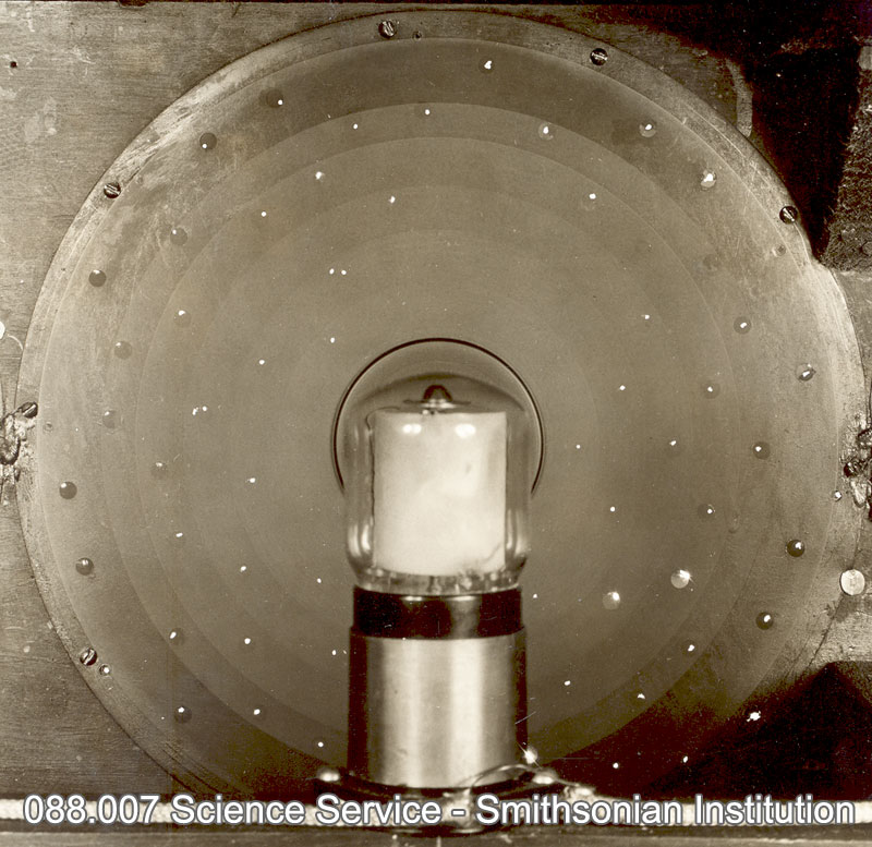
The Photona used a very simple system of twelve rotating light choppers, that worked to interrupt light periodically. Evidently no tone masks were used and the output was probably a complex wave. The twelve disks were cut radially with slots at several depths toward the centre of the disk, allowing for the production of harmonic or inharmonic overtones. The instrument is reported to have used 900 car lamps, switched on by keys, for the production of sound.8 “WCAU’s ’Photona’ Organ,” Electronics, April, 1905, p. 123. Thomas Rhea, again describes the function of the Photona:
“The lamps were connected, through different circuits, to the keyboard of two 73-note manuals and to “stops” which governed tone control. When a key on a manual was depressed, corresponding lamps were lit and the appropriate tone was “chopped” by the tone wheel. For timbre control, the partials of any tone could be varied in strength with knobs which increased or decreased the amount of current feeding into the appropriate lamps. Alternating current was used for keying these lamps; the Photona was constructed using no rectifiers (AC to DC converters ). Eremeeff was a designer with an car for musical nuance. In addition to the volume-control pedal that was standard fare for instruments of the era, he arranged for foot-operated control of vibrato amount. This was accomplished with a mechanical linkage that engaged a cam with a motor-driven gear; this in turn caused the displacement of the tone-generator drive belt on a cone- shaped pulley, creating true vibrato, as opposed to the constant-amount vibrato on some electronic musical instruments today. The Photona also had a “percussion push” button that caused a sudden rush of current to the photoelectric cells, creating a cracking, percussive sound. Maybe Eremeeff was trying to provide a rudimentary dynamic keyboard for touch-responsive phrasing. Even though the Photona had an impossibly complex tone generator, there were sparks of genius in its musical engineering.“9 Rhea, Thomas, L,(1984) Photo-Electric Instruments, The Art of Electronic Music – GPI Publications, 13.
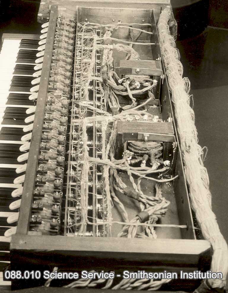
Photo-cell behind a revolving disc. Image: Smithsonian Institution Science Services.The WCAU Photona at the Smithsonian Institution: Image: Smithsonian Institution Science Services.The driving pulleys for the tone discs and transformers used for lighting and nine hundred six volt lamps. Image: Smithsonian Institution Science Services.
Ivan Eremeeff’s patents for a photo-electrical instrument 1934-6
Biography: Ivan Ivanovich Eremeef (1893 – ?)
Ivan Eremeeff (later Americanised to Ivan Jerome) was a Russian-American physicist, prolific inventor and designer of electronic instruments. Born in Chelyabinsk, Russia in 1893 , he probably emigrated to the USA about 1918, and began experimenting with the construction of electronic instruments about 1923 in Dayton, Ohio, where he also developed a four rotor H-1 helicopter for the US army (1922) a barograph (1928) and a mobile aircraft hangar (1922).
Eremeeff and Bothezat’s design for a four rotor military helicopter the ‘Flying Octopus’: December 18, 1922, The first helicopter actually to fly, designated the Engineering Division H-1, was designed by Dr. George de Bothezat and Mr. Ivan (Eremeeff) Jerome.
In 1930 he moved to Philadelphia, where he founded and chaired the Society of Electronic music and took out eight patents for electronic instruments between 1932 and 1936 including the including the Gnome (1933 patent), a larger variant of the Gnome (1933), the Syntronic Organ (1934) and the Photona (1935). In the early 1930s he worked at the electronic music laboratory of the radio station WCAU in Philadelphia.
Eremeeff’s electronic instruments were based on two different sound-generating systems: electromagnetic tone-wheels, a principle he used in the Gnome, and photoelectric devices – Photona (or WCAU organ; 1935) and Syntronic organ (1934). The last instrument was enthusiastically endorsed by Leopold Stokowski, and inspired him to plan with Eremeeff an electronic orchestra, but this project was never realized. In spite of their names, Eremeeff did not attempt to recreate the tone qualities of a pipe organ in either of his two photoelectric instruments. An unusual feature of all his electronic instruments was the addition of a vibrato pedal to the normal volume pedal, and in two of them there was also a control for the decay of the notes. Eremeeff claims to have experimented with prototypes of a Theremin like instrument intended to produce not only tones but light and odours. In the 1953 he filed a suit against Hammond Organ Co. for patent infringement of his ‘photoelectrical musical system’ which was ultimately dismissed for lack of prosecution in January 1957. 10Davies, Hugh (2014) Electronic Instruments, The Grove dictionary of musical instruments, New York : Oxford University Press, 167. 11Patent Suits. Notices under 35 U.S.C . 290 Patents act of 1952, 529.
In 1938 Eremeeff returned to aviation and created a design for a supersonic aircraft.12 Plane with the Speed of Sound Is Proposed by Designer, Popular Mechanics Magazine 1938-12: Vol 70 Iss 6, 833. After World War II, Eremeef/Jerome set up a lucrative business designing optical instruments and precision aerial cameras for the US army and moved to Southampton New York. In 1955, aged 62, Eremeev/Jerome hit the headlines when he was charged with creating obscene and pornographic films and corrupting minors at his Southampton mansion. Eremeev/Jerome jumped a $100,000 bail bond and fled the country. 131956, OBSCENE AND PORNOGRAPHIC LITERATURE AND JUVENILE DELINQUENCY INTERIM REPORT OF THE SUBCOMMITTEE TO INVESTIGATE JUVENILE DELINQUENCY TO THE COMMITTEE ON THE JUDICIARY PURSUANT TO S. Res. 62, and S. Res. 173 (84th Congress),7
References:
1
Davies, Hugh, (2014) Electronic Musical Instruments, The Grove dictionary of musical instruments, New York : Oxford University Press,168. ↩︎
2
Music of the Future now a Reality, Popular Mechanics, January 1936, 20-2. ↩︎
3
Kassell, Edward, E, (1934) A “Syntronic” Organ, Radio Craft, August 1934, 77,104-6. ↩︎
4
Eremeeff, Ivan, (1932), SYNTHETIC ELECTRICAL MUSICAL SYSTEM. US Patent 1,924,713, filed June 4, 1932 . ↩︎
5
Rhea, Thomas, L,(1984) Photo-Electric Instruments, The Art of Electronic Music – GPI Publications, 13. ↩︎
6
Davies, Hugh, (2014) Electronic Musical Instruments, The Grove dictionary of musical instruments, New York : Oxford University Press,168. ↩︎
7
Klos, Lloyd, E (1962) “Melody Mac” the Giant of the T.O. World, the Theatre Organ, 6. ↩︎
8
“WCAU’s ’Photona’ Organ,” Electronics, April, 1905, p. 123. ↩︎
9
Rhea, Thomas, L,(1984) Photo-Electric Instruments, The Art of Electronic Music – GPI Publications, 13. ↩︎
10
Davies, Hugh (2014) Electronic Instruments, The Grove dictionary of musical instruments, New York : Oxford University Press, 167. ↩︎
11
Patent Suits. Notices under 35 U.S.C . 290 Patents act of 1952, 529. ↩︎
12
Plane with the Speed of Sound Is Proposed by Designer, Popular Mechanics Magazine 1938-12: Vol 70 Iss 6, 833. ↩︎
13
1956, OBSCENE AND PORNOGRAPHIC LITERATURE AND JUVENILE DELINQUENCY INTERIM REPORT OF THE SUBCOMMITTEE TO INVESTIGATE JUVENILE DELINQUENCY TO THE COMMITTEE ON THE JUDICIARY PURSUANT TO S. Res. 62, and S. Res. 173 (84th Congress),7 ↩︎
Lesti (L) and Tiedemann’s (R) Trillion Tone Organ of 1931. Image: Radio Craft, January 1931.
The Radio Organ of a Trillion Tones (1931)
The Radio Organ of a Trillion Tones was created and developed by the Italian born electronic engineer Arnold Lesti and US inventor, F. Sammis in Hollywood, USA around 1931. The Radio Organ used a similar photo-electrical technique as the Celluphone, Superpiano and other variants and in Lesti’s later instruments – The Polytone(1934) and Singing Keyboard (1936) the designed with Frederick Sammis at RCA’s Phototone studios in Hollywood. 1Lesti, Arnold,(1931)Radio Organ of a Trillion Tones, radio Craft, january 1931, 402-3, 430.The The Radio Organ. however used a technique to generate more complex timbres than it’s rivals by projecting the light beam through two sets of glass disks – a ‘Pitch disk’ generating a pitched fundamental plus it’s ascending harmonics and a Timbre disk modifying the tone using a drawn representation of the sound wave of a real instrument (horn, violin, clarinet, oboe and a human voice). The principle was improved in Lesti and Sammis’ development of the Trillion Tone Organ called the Polytone. 2 Davies, Hugh, (2014), Radio Organ of a Trillion Tones, Grove Dictionary of Musical Instruments, Oxford University Press, 216.
Radio Craft Magazine’s impression of the Trillion Tone Organ. Image: Radio Craft, January 1931.Diagram of the photo-electrical technique of the Trillion Tone Organ. Image: Radio Craft, January 1931.
References:
1
Lesti, Arnold,(1931)Radio Organ of a Trillion Tones, radio Craft, january 1931, 402-3, 430. ↩︎
2
Davies, Hugh, (2014), Radio Organ of a Trillion Tones, Grove Dictionary of Musical Instruments, Oxford University Press, 216. ↩︎
The original Hammond Organ was Designed and built by the ex-watchmaker Laurens Hammond and John M Hanert in April 1935. Hammond set up his ‘Hammond Organ Company’ in Evanston, Illinois to produce electronic organs for the ‘leisure market’ and in doing so created one of the most popular and enduring electronic instruments ever built.
Hammond’s machine was designed using technology that relates directly to Cahill’s ‘Telharmonium’ of 1900, but, on a much smaller scale. The Hammond organ generated sounds in the same way as the Telharmonium, the tone wheel – The tone generator assembly consisted of an AC synchronous motor connected to a gear train which drove a series of tone wheels, each of which rotated adjacent to a magnet and coil assembly. The number of bumps on each wheel in combination with the rotational speed determined the pitch produced by a particular tone wheel assembly. The pitches approximate even-tempered tuning.
This method of creating tones was maintained until the mid 1960’s when transistors replaced tone wheels
The Hammond had a unique drawbar system of additive timbre synthesis (again a development of the Telharmonium) and stable intonation – a perennial problem with electronic instruments of the time. A note on the organ consisted of the fundamental and a number of harmonics, or multiples of that frequency. In the Hammond organ, the fundamental and up to eight harmonics were available and were controlled by means of drawbars and preset keys or buttons.A Hammond console organ included two 61-key manuals; the lower, or Great, and upper, or Swell, and a pedal board consisting of 25 keys. The concert models had a 32-key pedalboard. Hammond also patented an electromechanical reverb device using the helical torsion of a coiled spring, widely copied in later electronic instruments.
As well as being a successful home entertainment instrument, The Hammond Organ became popular with Jazz, Blues and Rock musicians up until the late 1970’s and was also used by ‘serious’ musicians such as Karlheinz Stockhausen in “Mikrophonie II”
The Hammond Novachord was manufactured by the Hammond Organ Co in the USA from 1939 to 1942, designed by Laurens Hammond, John Hanert and C.N.Williams. A total of 1096 models were built.The Novachord was a polyphonic electronic organ and was Hammonds first electronic tube based instrument – a departure from his usual tone-wheel designs. The Novachord was a much more complex instrument than the Solovox Hammond’s other electronic tube-based instrument. The Novachord had 169 vacuum tubes to control and generate sound and was played on a seventy two note keyboard with a simple pressure sensitive system that allowed control over the attack and timbre of the note. The sound was produced by a series of 12 oscillators that gave a six octave range using a frequency division technique; the Novachord was one of the first electronic instruments to use this technique which was later became standard in electronic keyboard instruments.
Novachord fron panel
The front panel of the instrument had a series of 14 switch-able rotary knobs to set the timbre, volume, ‘resonance’,bass/treble, vibrato (six modulation oscillators were used) and ‘brightness’ of the sound. A set of 3 foot operated pedals controlled sustain,and volume the third pedal allowing control of the sustain by either foot. The final signal was passed to a pre-amplifier and then to a set of internal speakers. The Novachord was able to produce a range of sounds imitating orchestral instruments such as the piano, harpsichord, stringed and woodwind instruments as well as a range of it’s own new sounds. In May 1939 ‘The Novachord Orchestra’ of Ferde Grofé performed daily at the Ford stand at the New York World Fair with four Novachords and a Hammond Organ and in Adrian Cracraft’s ‘All Electronic Orchestra’, the Novachord also featured in several film scores (Hans Eisler’s “Kammersinfonie” 1940) but seems to have fallen from favour due to the instability of it’s multiple tube oscillators and playing technique. The Novachord was discontinued in 1942. A Hammond employee comments:
“The Novachord made beautiful music if played well, but it was not well adapted either to either an organists style or a pianists style. Thus it required development of a specific style, which not many musicians were prepared to do. it also had technical problems, requiring frequency adjustments to keep it operating chiefly because the frequency dividers and electronic components before the war were not nearly as good as those available in later years. The hammond Organ Company could have revived it after the war, and could have made it better in light of available technology at the time, but sales had been disappointing ad so it was not considered a good commercial product”
The Hammond Novachord from a 1940s promotional brochure. Image :Dan Wilson, Hideaway Studio (www.hideawaystudio.co.uk)
Laurens Hammond and the Novachord in ‘Popular Mechanics’ magazine USA 1939The Novachord in ‘Popular Mechanics’ magazine USA 1939
Hammond Novachord in “New Horizons” 1940
A restored Novachord
Novachord Orchestra: Introduction of The Hammond Novachord at the New York World’s Fair 1939 – 1940.
Sources:
F.D.Merril jr: “The Novachord”, Electronics,xii/11 (1939),16
The Vocoder (Voice Operated reCorDER) and Voder (Voice Operation DEmonstratoR)) developed by the research physicist Homer Dudley, was invented as a result of research into compression techniques for telephone voice encryption at Bell Laboratories, New Jersey USA and was the first successful attempt at analysing and resynthesising the humans voice.
The machine consisted of an analyser and a synthesiser. the analyser detected energy levels of successive sound samples measured over the entire audio frequency spectrum via a series of narrow band filters. The results of which could be viewed graphically as functions of frequency against time. The synthesiser reversed the process by scanning the data from the analyser and supplying the results to a feedback network of analytical filters energised by a noise generator to produce audible sounds.
The fidelity of the machine was limited; the machine being intended as a research machine for voice over copper-wire phone transmissions. However, Werner Meyer-Eppler, then the director of Phonetics at Bonn University, recognised the relevance of the machines to electronic music after Dudley visited the University in 1948, and used the vocoder as a basis for his future writings which in turn became the inspiration for the German “Electronische Musik” movement.
The Voder was first unveiled in 1939 at the New York World Fair (where it was demonstrated at hourly intervals) and later in 1940 in San Francisco. There were twenty trained operators known as the ‘girls’ who handled the machine much like a musical instrument such as a piano or an organ, but they managed to successfully produce human speech during the demonstrations. In the New York Fair demonstration, which was repeated frequently, the announcer gave a simple running discussion of the circuit to which the girl operator replied through the Voder. This was done by manipulating fourteen keys with the fingers, a bar with the left wrist and a foot pedal with the right foot.
“At the 1939 World’s Fair a machine called a Voder was shown . A girl stroked its keys and it emitted recognsable speech. No human vocal cords entered into the procedure at any point; the keys simply combined some electronically produced vibrations and passed these on to a loud-speaker.”
(“As We May Think” by Vannevar Bush, 1945. )
The Solovox was designed by engineers Alan Young, John Hanert, Laurens Hammond (speaker cabinet) and George Stephens of the Hammond Organ Co and manufactured in the United States between 1940 and 1948. The Hammond Solovox was a monophonic ‘keyboard attachment’ instrument intended to accompany the piano with organ type lead voices – similar to the Clavioline and Tuttivox. The three octave short keyed keyboard was stored on a sliding mounting under the piano keyboard with a knee operated volume control. The instrument was connected to an electronic sound generation box, amplifier and speaker housing by three thick cables and derived it’s sound from a single LC oscillator with a one octave frequency range – the signal from which was then passed through a series of 5 frequency dividers to create a further two octaves.
Hammond Solovox
The Solovox (J+K models) used two vibrating metal reeds modulate the oscillator frequency to create a vibrato effect, in later models this was replaced by a second oscillator acting as a vibrato oscillator.On the front of the instrument below the keyboard there were a series of large thumb operated buttons for oscillator range (switchable +/- 3 octaves: ‘soprano’, ‘contralto’,’tenor’ , ‘bass’), vibrato, attack time, ‘deep tone’, ‘full tone’, ‘1st voice’, 2nd voice’, ‘brilliant’ and a switch for selecting woodwind, string sound or mute. The Solovox was able to create a range of string, woodwind and organ type sounds and was widely used in light music of its time.
A 1942 photograph of the Electric Automatic Orchestra at the Hammond Sound Studio, Chicago with john Hanert at the controls. Showing (L) the ‘Time Sequence’ table and scanning carriage and (R) a bank of some of the vacuum tube tone generators. Photograph; Private collection of Douglas Jackson 2017.
Once the phonograph had supplanted radio and the pianola as the predominant format for music sales in the 1930s, attention turned to refining and accelerating the production and manufacture of records. 1Dolan, Brian. Inventing Entertainment: The Player Piano and the Origins of an American Music Industry. Rowman & Littlefield Publishers Inc 2009.Hammond Organ Inc’s chief Designer John M. Hanert – who was responsible for the design of the hugely successful tonewheel ‘Hammond Organ’ series as well as the vacuum tube based ‘Solovox’ and ‘Novachord’ instruments – was contemplating a self-contained device that could be used as a composition system, sound synthesiser and gramophone production tool:
“My invention relates generally to apparatus for production as sound or as a signal for recording purposes, without the employment of musicians in anyway whatsoever.” 2 John M Hanert US Patent 2,541,051 Apparatus for automatic production of music,Feb. 13, 1951.
The result of Hanert’s experiment was the Electric Automatic Orchestra; a large, room sized machine installed at the Hammond Instrument Inc. sound studios at 2915 North Western Ave Chicago Illinois. The basic function of the machine were divided into three parts; a composition ‘Time Sequence’ table where the composer could write musical notation into the machine, a synthesis module which created sounds from the notation, and an output – in this case a lacquer disc-lathe to cut master recordings.
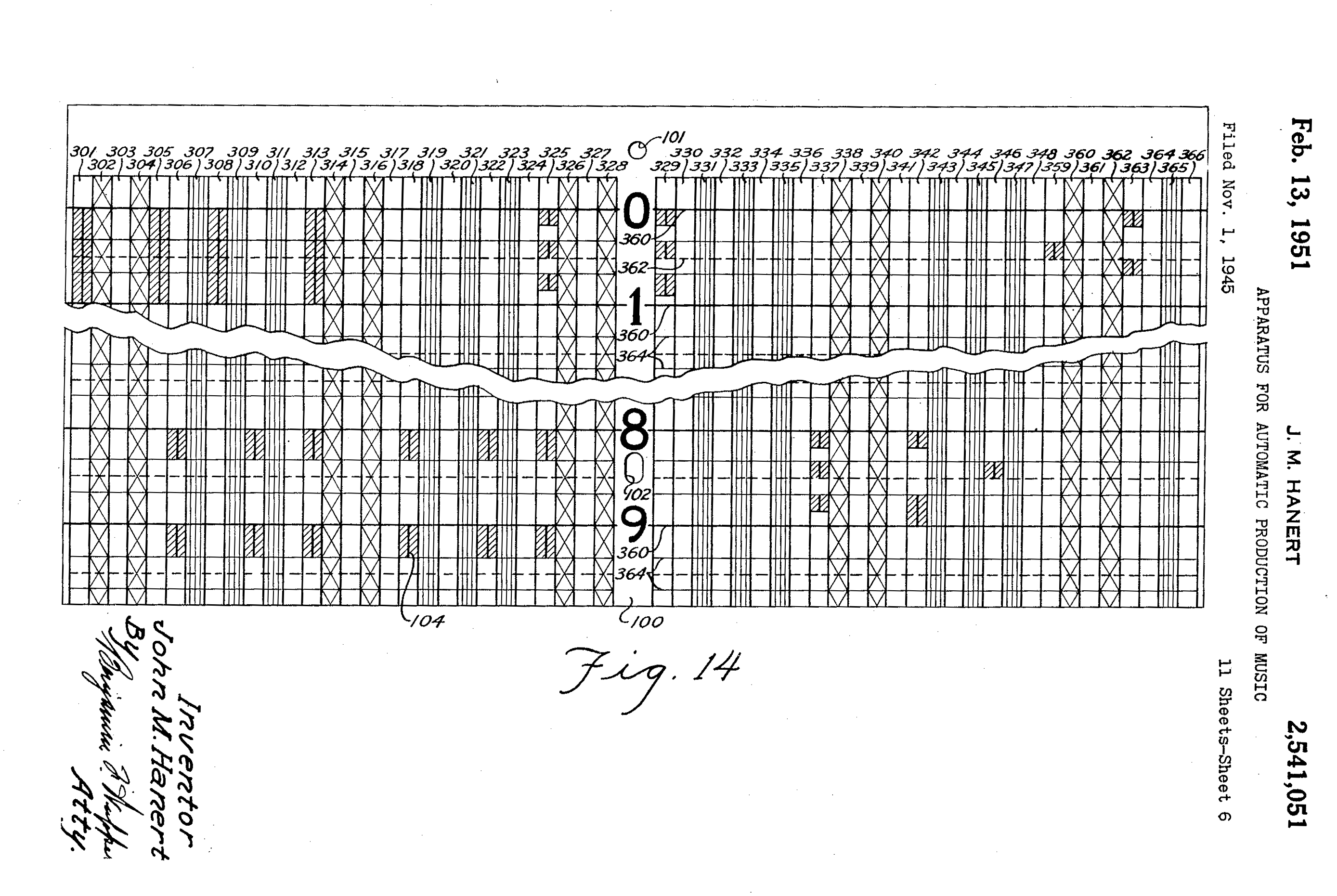
Diagram illustrating the notation card template with pitch on the X axis and duration/position on the Y axis. The scanning head travelled along the Y axis. (US Patent 2,541,051A 1945)
The ‘Time Sequence’ section was an eighteen meter table – extendable to the amount of room-space available – covered with overlapping ‘record notation’ cards of approximately 28 X 30 cm. These cards could be drawn on with conductive graphite or aquadag marks representing musical information. Above the table travelled a wheeled electric-motor driven ‘scanning carriage’ equipped with multiple phosphor-bronze contact brushes. When the brushes made contact with the conductive graphite marks on the cards below, an electronic signal was generated that triggered the relevant musical reaction in the sound generating part of the instrument. (Hanert also provided an alternate photoelectric set of scanning heads which could replace the contact brushes.)
Hanert’s design enabled the composer to a create ‘perfect’ compositions by writing, erasing and re-writing the music on the ‘Time Sequence’ table – which could be done on or off-site or as required. Once this perfect composition had been achieved, the machine could make a final run and cut a master recording to disc to be used for mass production.3 Rhea, Tom. ‘The Hanert Synthesizer’ Electronic Perspectives, Contemporary Keyboard September 1979 p78.
The record notation cards were pre-printed with a grid like template and could be marked to represent individual note pitch – measured in quarter tones, envelope, timbre, vibrato, position in the bar and volume as well as overall instrument volume. The final tempo of the piece could be controlled by simply varying the speed of the rail driven scanning carriage as it travelled along the table or paused, reversed or ‘looped’ by control marks on the cards. The length of the table defined the length of the piece, which on this model, consisted of 39 cards giving a maximum playing length of 96 bars.4T.L.Rhea:”The Evolution of Electronic Musical Instruments in the United States” (diss., George Peabody College, Nashville, Tenn, 1972)
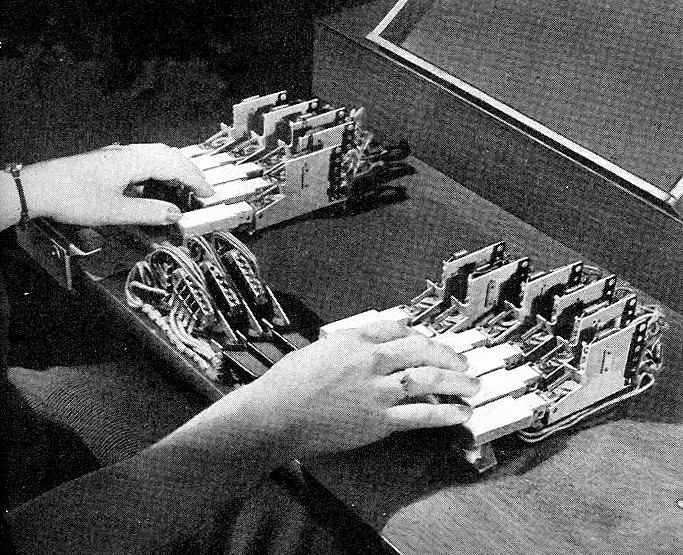
1942 Photograph of the electronic scanning heads of the Hanert Electrical Orchestra. Photo; Private collection of Douglas Jackson 2017.1942 Photograph of the electronic scanning heads of the Hanert Electrical Orchestra. Photo; Private collection of Douglas Jackson 2017.1942 Photograph of the electronic scanning heads of the Hanert Electrical Orchestra. Photo; Private collection Thom Rhea
The tones themselves were created by six separate banks of polyphonic vacuum tube generators similar in design to Hanert’s Novachord (USA, 1940). The instrument was also able to create percussive xylophone and drum sounds created by random (white noise) generators. Combinations of sounds could be defined on the notation cards allowing the composer to immediately switch instrument sounds as the piece progressed.
1942 Photograph of the tone generators of the Hanert Electrical Orchestra. Photo; Private collection of Douglas Jackson 2017.1942 Photograph of the tone generators of the Hanert Electrical Orchestra. Photo; Private collection of Douglas Jackson 2017.
Hanert’s instrument was unique in that for the first time a composer/producer could work in a nonlinear fashion: the composition cards could be erased or deleted simply by rubbing out the graphite mark or removing the card. Cards could be arranged in any order, enabling the composer to mix, transpose and reverse music themes and sounds, instrumentation could be changed at any point or applied to any written part of the composition. And, Hanert’s machine allowed the composer/producer the ability to monitor the results of the editing almost immediately. Hanert compared this facility to the practice of a visual artist:
The difficulties inherent in the orchestral production of a composition may be compared to those which would confront an artist who found it necessary in painting a picture to destroy the complete or partially complete picture he was painting every time he became dissatisfied with any slight detail of the picture. The painter is not subject to such stringent regulation but instead merely repaints such minor portion of the whole picture which does not represent the subject being painted sufficiently accurately to meet his artistic approval…In the method and apparatus of this invention the composer, arranger, or conductor has at his command means for controlling the quality of each note, its intensity, intensity envelope, the degree of accent, duration, and tempo without necessarily affecting any other note or tone of the composition.5US Patent 2,541,051A 1945,4.
Diagram from Hanert’s patent describing the sequence of tone filters and processors.
Despite its innovative qualities, the Electric Automatic Orchestra was never used commercially as Hanert had intended. In fact it seems that it was only ever used by Hanert himself and was not taken seriously by the Hammond company – who tended to humour Hanert’s ‘technical eccentricities’ in order to maintain his interest in more mundane but commercial designs. In addition to Hammond’s lukewarm support, the commercial failure of the project was also down to a combination of the synthetic nature of its sound, the inability of composers of the day to grasp the new musical paradigm the instrument offered plus the ever increasing capability and quality of recording technology– microphones, mixing desks, magnetic pick-ups, tape recorders – made the need for such a solution less pressing. The Electric Automatic Orchestra was sidelined and eventually mothballed by the Hammond company sometime during the 1950s.
Shortly after the disappearance of Hanert’s machine, David Sarnoff, chairman of RCA corporation, commissioned a self-contained commercial music production machine that could mathematically analyse and re-synthesise pop music.
“Composers don’t need to be able to play an instrument because our synthesizer will allow them to create any kind of music they want…Musicians aren’t required if you have our synthesizer.”6 David Sarnoff, chairman of RCA during the 1950s. Excerpt From: Vail, Mark. The Synthesizer, Oxford University Press, 2014, p271.
What became known of as the RCA Synthesiser (the first time ‘Synthesiser’ was used in a musical context) was installed at the Columbia–Princeton Electronic Music Center and directly referenced Hanert’s work (8). The machine used the same, though perhaps less flexible structure; a three stage process of music production – in this case a paper punch roll for composition, multiple banks of vacuum tubes for sound synthesis, and the same lacquer disc lathe for musical output.
Biography: John Marshall Hanert
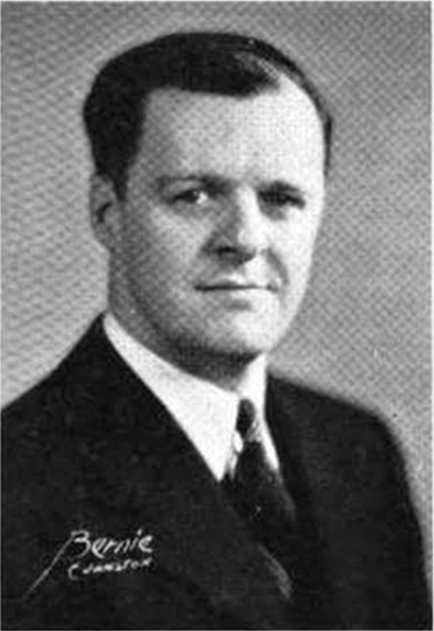
John Marshall Hanert was born into a German-American family on 18th March 1909 in Milwaukee, Wisconsin. In 1932 Hanert was awarded a B.S. in Engineering and a BSE in Physics at The University of Michigan. An accomplished organist, Hanert had a special interest in electronic musical instruments and after graduation began working with Richard Ranger – inventor of the Rangertone Organ amongst other electronic musical devices – in New York on a Photo-Electrical musical instrument. In 1934 Hanert was appointed as the Head of Research at the Hammond Organ Inc in Chicago where he spent the rest of his life as the chief designer of all of Hammond’s instruments; Hanert became known as the musically untrained Laurens Hammond’s ‘Ears’.Hanert was the co-inventor on the first Hammond tone-wheel organ and inventor of the Solovox (1938) and Novachord (1939–42) one of the world’s first commercial synthesisers as well as many patents for vibrato and reverberation audio processors. Hanert continued working at the company After Laurens Hammond’s retirement in 1958 until he died on 23rd June 1962 at the age of 53 in a car accident near New Munster Wisconsin.7‘The Michigan Alumnus’ vol LXIX 1962-1963 page 63. Private collection of Douglas Jackson 2017.
References:
1
Dolan, Brian. Inventing Entertainment: The Player Piano and the Origins of an American Music Industry. Rowman & Littlefield Publishers Inc 2009. ↩︎
2
John M Hanert US Patent 2,541,051 Apparatus for automatic production of music,Feb. 13, 1951. ↩︎
The Electronic Music Box was a synthesis and composition device designed and built as a personal project by Dr Earle.L.Kent while employed at the C.G.Conn Ltd Company, USA, to design electric organ circuits.1Margaret Downie Banks, Dynamic Research: Earle L. Kent and Conn’s Research Department, National Music Museum,The University of South Dakota. The Music Box was an analogue ‘beat frequency’ vacuum tube based synthesiser controlled by a punched paper strip device as used previously in the 1930’s by instruments such as Coupleaux’s Givelet and later, the RCA mkII and Siemens Synthesiser amongst others. The punch paper strip was a system similar to a ‘pianola’ paper reader and allowed the composer to produce musical sequences that were beyond the manual dexterity of the performer:
“The goals established for the music Box involved wider flexibility of performance than is possible in any conventional musical instrument. It was felt that it should not be confined to the usual limitations of manual keying. It should be capable of grater speed and wider combinations than are possible by manual or pedal dexterity, and it should not be limited to the equally tempered scales as are most keyed instruments. It was recognised that virtually any speed or combination could be obtained by keying with a perforated paper roll with the loss of some of the vital control usually exercised by a musician while making music and also with the loss of its conventional acceptance as a musical instrument. However, it was felt that a musician usually “records” his manual manipulation rather precisely in his brain before a concert by repetitive rehearsal and that the losses by recording this operation on paper would be exceeded by the gains”
Dr Earle.L.Kent
Dr Earle Kent at the C.G.Conn Ltd CompanyLabs c 1950
Although based on the established ‘beat frequency’/heterodyning principle, Kent’s instrument employed a more complex system of frequency changers to create a more interesting range of timbre and control over the shape of the note. The Music Box was designed to allow control off the ‘slurring’ of the note, formant filtering control and control of volume and depth and rate of tremolo. The Electronic Music Box was influential on the development of electronic musical instruments, Dr Kent was visited by Harry Olson who later adapted features of his RCA synthesiser to incorporate functions of the Music Box, but the Conn company chose not to exploit the commercial possibilities of the instrument.
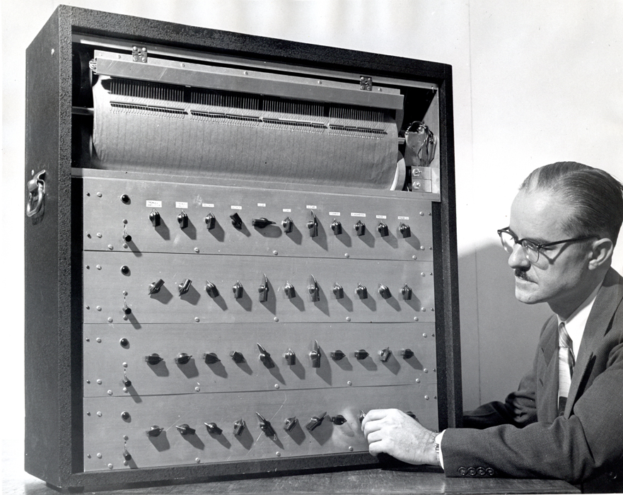
Percy Grainger (L) and Earle Kent (R) with and ‘Dr Kent’s Electronic Music Box’ at Kent’s Research Engineering Department for the Conn Company, Elkhart, USA. image: Grainger Museum Archive, 99.6700.1
The Australian ‘Free Music’ composer Percy Grainger contacted Earle Kent shortly after Kent had completed his PhD at the University of Michigan. Grainger was looking for an instrument that would be suitable for his concept of free music:
“Play any pitch of any size, half, quarter or eighth tones, within the range of 7 voices, to be able to pass from pitch to pitch by way of a controlled glide as well as by leap, to play precisely controlled, complex irregular rhythms past the scope of human execution.”
Grainger visited Kent’s research department at the Conn Musical Instrument Company in Ekhart USA in 1951 to witness the Electronic Music Box which shared many features of Grainger’s somewhat crude constructions. However for undisclosed reasons, Grainger was unsatisfied with the Music Box and returned to his own Free Music experiments in Australia.2Grainger Museum Archive. https://omeka.cloud.unimelb.edu.au/grainger/
References
1
Margaret Downie Banks, Dynamic Research: Earle L. Kent and Conn’s Research Department, National Music Museum,The University of South Dakota. ↩︎
2
Grainger Museum Archive. https://omeka.cloud.unimelb.edu.au/grainger/ ↩︎