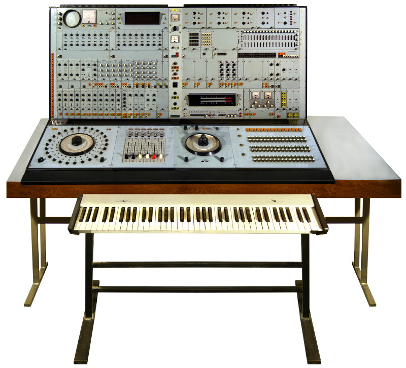
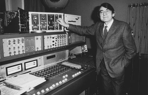
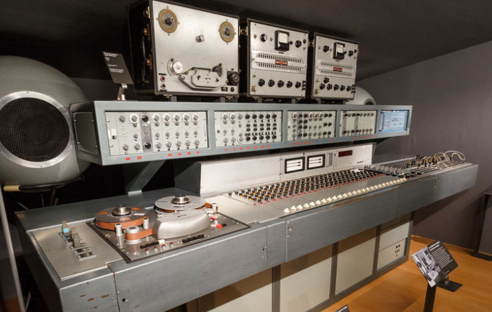
The ASYZ 2.0 ‘Analyzátor a syntezátor zvuku’ at the Barrandov Film Studio 1971
The ASYZ was built in the late 1960s at the ‘East European Hollywood’ Barrandov Film Studios in Prague to provide sound effects and electronic music for film productions, with the final version, the ASYZ2 completed in 1971. The instrument was designed by electronic engineers, Antonín ka [name incomplete], Bohumil Matoušek and later by the sound engineer and designer Pavel Pitrák who maintained the instrument throughout the seventies and eighties. The ASYZ remained in use until the 1990s and is now housed at the collection of the Cinepost post production company, Praha.
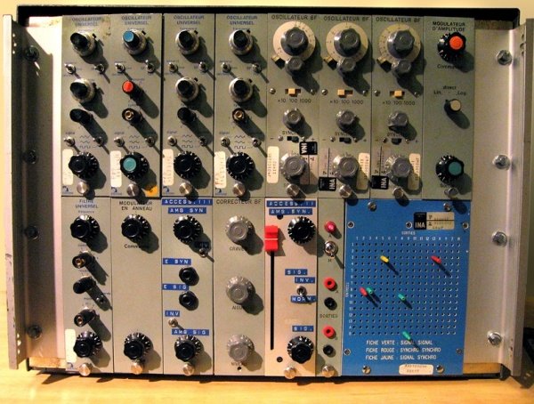
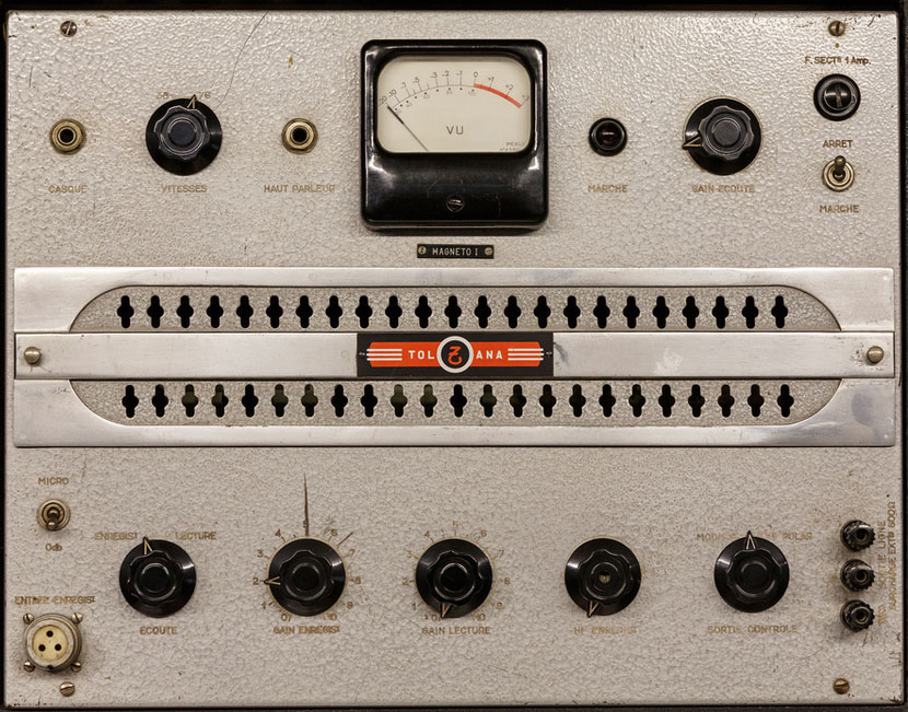
The original design was a keyboard-less modular type device intended to be used for processing external audio signals and for generating sound effects, the modules being connected using colour coded patch cables. The instrument was controlled by manually switching a rotary dial to select different timbres and pitches or by programming a 16 step three track sequencer, a six octave keyboard was added in the 1990s. The modules of the ASYZ included a Voltage Controlled Oscillator, white noise generator, low and high pass filters, a parametric equaliser, ring modulator, phaser, signal mixer, VCA, ADSR envelope shaper, LFO, random signal generators, envelope followers and auxiliary circuits. The output of the instrument was controlled by a small six-channel mixing console and monitored using a built-in oscilloscope.
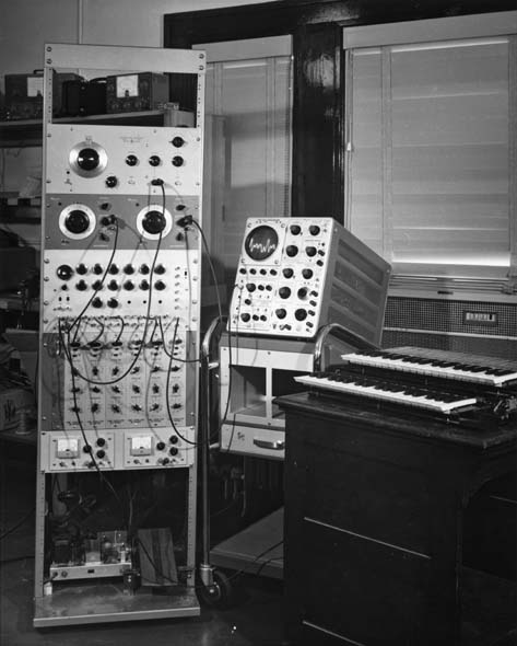
EMS was the London electronic music studio founded and run by Peter Zinovieff in 1965 to research and produce experimental electronic music. The studio was based around two DEC PDP8 minicomputers, purportedly the first privately owned computers in the world.
One of the DEC PDP8 mini-computers at EMS
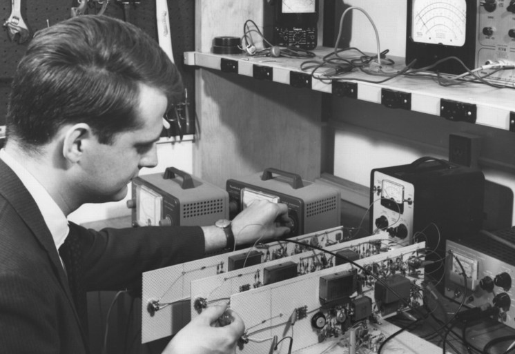
Digital signal processing was way beyond the capabilities of the 600,000 instructions-per-second, 12k RAM, DEC PDP8s; instead, Peter Grogono was tasked with developing a new musical composition and ‘sequencing’ language called MUSYS. MUSYS was designed to be an easy to use, ‘composer friendly’ and efficient (i.e. it could run within the limitations of the PDP8 and save all the data files to disk – rather than paper tape) programming language to make electronic music. MUSYS, written in assembly language, allowed the PDP8s to control a bank of 64 filters which could be used either as resonant oscillators to output sine waves, or in reverse, to read and store frequency data from a sound source. This meant that MUSYS was a type of low resolution frequency sampler; it could ‘sample’ audio frequency data at 20 samples per second and then reproduce that sampled data back in ‘oscillator mode’. MUSYS was therefore a hybrid digital-analogue performance controller similar to Max Mathew’s GROOVE System (1970) and Gabura & Ciamaga’s PIPER system (1965) and a precursor to more modern MIDI software applications.
“It all started in 1969, when I was working at Electronic Music Studios (EMS) in Putney, S.W. London, UK. I was asked to design a programming language with two constraints. The first constraint was that the language should be intelligible to the musicians who would use it for composing electronic music. The second constraint was that it had to run on a DEC PDP8/L with 4K 12-bit words of memory.”
The two PDP8’s were named after Zinovieff’s children Sofka (an older a PDP8/S) and Leo (a newer, faster a PDP8/L). Sofka was used as a sequencer that passed the time-events to the audio hardware (the 64 filter-oscillators, six amplifiers, three digital/analog converters, three “integrators” (devices that generated voltages that varied linearly with time), twelve audio switches, six DC switches, and a 4-track Ampex tape-deck). Leo was used to compute the ‘score’ and pass on the data when requested by Sofka every millisecond or so;
“These devices could be controlled by a low-bandwidth data stream. For example, a single note could be specified by: pitch, waveform, amplitude, filtering, attack rate, sustain rate, and decay time. Some of these parameters, such as filtering, would often be constant during a musical phrase, and would be transmitted only once. Some notes might require more parameters, to specify a more complicated envelope, for instance. But, for most purposes, a hundred or so events per second, with a time precision of about 1 msec, is usually sufficient. (These requirements are somewhat similar to the MIDI interface which, of course, did not exist in 1970.)”
Previous to the development of MUSYS, the EMS PDP8s were used for the first ever unaccompanied performance of live computer music ‘Partita for Unattended Computer’ at Queen Elizabeth Hall, London, 1967. Notable compositions based on the MUSYS sytem include: ‘Medusa’ Harrison Birtwistle 1970, ‘Poems of Wallace Stevens’ Justin Connolly. 1970, ‘Tesserae 4’ Justin Connolly 1971, ‘Chronometer’ Harrison Birtwistle 1972, ‘Dreamtime’ David Rowland 1972, ‘Violin Concerto’ Hans Werner Henze 1972.
Audio Examples
Demonstrating the digital manipulation of a voice with the frequency sampler:
‘In the Beginning‘ PeterGrogono with Stan Van Der Beek 1972. “In 1972, Stan Van Der Beek visited EMS. Peter Zinovieff was away and, after listening to some of the things we could do, Stan left with brief instructions for a 15 minute piece that would “suggest the sounds of creation and end with the words ‘in the beginning was the word'”. All of the sounds in this piece are derived from these six words, heard at the end, manipulated by the EMS computer-controlled filter bank.”
A composition consisting of a single note might look like this:
      #NOTE 56, 12, 15;
      $
The note has pitch 56 ( from an eight-octave chromatic scale with notes numbered from 0 to 63), loudness 12 (on a logarithmic scale from 0 to 15), and duration 15/100 = 0.15 seconds. The loudness value also determines the envelope of the note.
An example of a MUSYS program that would play fifty random tone rows:
      50 (N = 0 X = 0
      1  M=12^  K=1  M-1 [ M (K = K*2) ]
         X & K[G1]
         X = X+K  N = N+1  #NOTE M, 15^, 10^>3;
         12 - N[G1]
      $
MUSYS evolved in 1978 into the MOUSE programming language; a small, efficient stack based interpreter.
The ARP Synthesiser company was started by the engineer and musical enthusiast Alan Robert Pearlman – hence ‘ARP’ – in 1970 in Lexington, Massachusetts, USA. Previous to ARP, Pearlman had worked as an engineer at NASA and ran his own company Nexus Research laboratory Inc., a manufacturer of op-amps (precision circuits used in amplifiers and test equipment) which he sold in 1967 to fund the launch of the ARP company in 1969. The inspiration for ARP came after he played with both Moog and Buchla synthesisers and being unimpressed by the tuning instability of the oscillators and lack of commercial focus – especially the keyboardless Buchla Box – and became determined to produce a stable, friendly, commercial electronic instrument.1Trevor Pinch, Frank Trocco, (2004) Analog Days: The Invention and Impact of the Moog Synthesizer, Harvard University Press.
“If you would like to spend your time creatively, actively producing new music and sound, rather than fighting your way through a nest of cords, a maze of distracting apparatus, you’ll find the ARP uniquely efficient . . . matrix switch interconnection for patching without patch cords…P.S. The oscillators stay in tune.”
ARP Advert 1970
The companies first product was the ARP 2500, a large monophonic modular voltage-controlled synthesiser designed along similar lines to the Moog Modular series 100. The 2500 had a main cabinet holding up to 12 modules and two wing-extension adding another six modules each. The interface was designed to be as clear as possible to non-synthesists with a logically laid out front panel and, unlike the Buchla and Moog Modular, dispensed with patch cables in favour of a series of 10X10 slider matrices, leaving the front panel clear of cable clutter. The 2500 also came with a 10-step analogue sequencer far in advance of any other modular system of the day
Despite the fact that the 2500 proved to be an advanced, reliable and user-friendly machine with much more stable and superior oscillators to the Moog, it was not commercially successful, selling only approximately 100 units.
Modules of the ARP 25002Peter Forrest, (1994) The A-Z of Analogue Synthesizers, Susurreal Publishing, Devon, England
Module #
Type of Module
Description
1002
power supply
1003
dual envelope generator
This module contains two ADSR envelope generators (actually labeled “Attack”, “Initial Decay”, “Sustain”, and “Final Decay”), each switchable between single or multiple triggering. There is a manual gate button as well as a front panel input for gate/trigger and a back panel input for a sustain pedal.
1003a
dual envelope generator
(same as 1003, except re-positioned trigger switches and gate buttons)
1004
VCO
A Voltage Controlled Oscillator with a range from 0.03Hz to 16kHz, this module can function as a VCO or an LFO. It features separate outputs for each of its five waveforms (sine, triangle, square, sawtooth, and pulse) and 6 CV (control voltage) inputs, as well as a CV input for Pulse Width Modulation.
1004p
VCO
This module is the same as the 1004, except each waveform has its own attenuation knob for mixing all the waveforms together. There is a separate output to for the mixed waveforms.
1004r
VCO
This module is the same as the 1004, except each waveform has its own rocker switch to route any or all of the waveforms to an extra mix output.
1004t
VCO
This module is the same as the 1004r, except it uses toggle switches.
1005
VCA andRing Modulator
This module is half Voltage Controlled Amplifier and half Balanced (Ring) Modulator. It is switchable between linear or exponential voltage control, and features 11 inputs, 3 outputs, and illuminated push-buttons.
1006
VCF and VCA
The Voltage Controlled Filter (24dB/octave, low-pass, with resonance) and Voltage Controlled Amplifier (switchable between linear and exponential) in one module
1012
Convenience Module
This module routes two jack inputs to any of the upper ten lines of the lower matrix. (Remember, most of the patching for this instrument is done from these matrix sliders).
1016
dual noise generators
This module features two random voltage generators outputting white or pink noise and two slow sample-and-hold circuits, four outputs in all.
1023
dual VCO
Both oscillators feature the same waveforms as 1004 with a switch for high and low frequency ranges. There are a total of 10 control inputs and 2 audio outputs.
1026
Preset Voltage module
This module contains eight manually or sequencer-driven gated control-voltages, each with two knobs sending control voltages to separate outputs. It can be connected, via the rear panel, to module 1027 Sequencer or module 1050 Mix-Sequencer.
1027
Sequencer
This is a 10X3 sequencer with 14 outputs (including 10 separate position/step gates), 6 inputs, buttons for step and reset, and a knobs for pulse repetition/width, which controls the silence between the steps.
1033
Dual Delayed-Trigger Envelope Generator
This module is the same as the 1003 ADSR module except it has two more knobs to control gate delay.
1036
Sample-and-Hold / random voltage
1045
Voice Module
This all-in-one module contains a VCO, VCF, VCA, and two ADSR envelope generators, as well as 16 inputs, and four outputs. (Note: Most modules feature a spelling mistake “Resanance” instead of “Resonance”.)
1046
quad envelope generator
This module is basically a 1003 and a 1033 combined into one module.
1047
Multimode Filter / Resonator
This module features 15 inputs, 4 outputs and an overload warning light.
1050
Mix-Sequencer
This module features two 4X1 mixers with illuminated on/off buttons.
3001
Keyboard
This keyboard features a 5-octave, 61-note (C-C) keyboard with the bottom two octaves (C-B) reverse colored to show the keyboard split. The top half of the keyboard is duophonic. There are separate CV (1v/octave), gate, and trigger outputs for each side of the split, as well as separate panels on either side of the keyboard with controls for portamento, tuning, and pitch interval.
The ARP 2600 was designed to be a commercially viable portable, semi-modular analog subtractive synthesiser with built in modules i.e. a versatile but not-too-complicated synthesiser, targeted at the educational market; schools, universities and so-on. The inbuilt modules could be patched using a combination of patch cables or by using sliders to control internally hard wired connections:
“ARP 2600 The ultimate professional-quality portable synthesizer Equally at home in the electronic music studio or on stage, the ARP 2600 provides the incredible new sounds in today’s leading rock bands The 2600 is also owned by many of the most prestigious universities and music schools in the world Powerful. dependable, and easy to play. the 2600 can be played without patchcords or modified with patch cords. This arrangement provides maximum speed and convenience for live performance applications, as well as total programming flexibility for teaching, research composition and recording. An pre-wired patch connection(s) can be overridden by simply inserting a patchcord into the appropriate jack on the front panel.
The ARP 2600 is easily expanded and can be used with the ARP 2500 series.Renowned for its electronic superiority, the oscillators and filters in the 2600 are the most stable and accurate available anywhere Accompanied by the comprehensive, fully illustrated owner s manual, the ARP 2600 is recognized as the finest, most complete portable synthesizer made today
FUNCTIONS:
3 Voltage Controlled Oscillators 03 Hz to 20 KHz in two ranges Five waveforms include: variable-width pulse. triangle. sine, square, and sawtooth
1 Voltage Controlled Lowpass filter Variable resonance, DC coupled. Doubles as a low distortion sine oscillator.
1 Voltage Controlled Amplifier Exponential and linear control response characteristics
1 Ring Modulator. AC or DC coupled
2 Envelope Generators.
1 Envelope Follower.
1 Random Noise Generator. Output continuously variable from flat to -6db/octave
1 Electronic Switch, bidirectional
1 Sample & Hold with internal clock.
1 General purpose Mixer and Panpot.
1 Voltage Processor with variable lag.
2 Voltage Processors with inverters
1 Reverberation unit. Twin uncorrelated stereo outputs
2 Built-in monitoring amplifiers and speakers, with standard stereo 8-ohm headphone jack.
1 Microphone Preamp with adjustable gain
1 Four-octave keyboard with variable tuning. variable portamento, variable tone interval, and precision memory circuit.
DIMENSIONS: Console 32″ x 18″ x 9x Keyboard 35″ x 10″ x 6″ WEIGHT: 58 Ibs” 3ARP 2600 Promotional material 1971
ARP 2600 white version
ARP 2800 ‘Odyssey’ 1972
By the mid-1970s ARP had become the dominant synthesiser manufacturer, with a 40 percent share of the $25 million market. This was due to Pearlman’s gift for publicity – the ARP2500 famously starred in the film ‘Close Encounters of the Third Kind’ (1977) as well as product endorsements by famous rock starts; Stevie Wonder, Pete Townsend, Herbie Hanckock and so-on – and the advent of reliable, simpler, commercial instrument designs such as the ARP 2800 ‘Odyssey’ in 1972.
ARP 2800 Odyssey
The ARP 2800 ‘Odyssey’ 1972-1981
The Odyssey was ARP’s response to Moog’s ‘Minimoog’; a portable, user-friendly, affordable performance synthesiser; essentially a scaled down version of the 2600 with built in keyboard – a form that was to dominate the synthesiser market for the next twenty years or so.
The Odyssey was equipped with two oscillators and was one of the first synthesisers to have duo-phonic capabilities. Unlike the 2600 there were no patch ports, instead all of the modules were hard wired and routable and controllable via sliders and button son the front panel. ‘Modules’ consisted of two Voltage Controlled Oscillators (switchable between sawtooth, square, and pulse waveforms) a resonant low-pass filter, a non-resonant high-pass filter, Ring Modulator, noise generator (pink/white) ADSR and AR envelopes, a triangle and square wave LFO, and a sample-and-hold function. The later Version III model had a variable expression keyboard allowing flattening or sharpening of the pitch and the addition of vibrato depending on key pressure and position.4Mark Vail, (2000), Vintage Synthesizers: Pioneering Designers, Groundbreaking Instruments, Collecting Tips, Mutants of Technology, 2000 by Backbeat Books.
ARP 2800 Odyssey MkI
ARP Production model timeline 1969-1981:
1969 – ARP 2002 Almost identical to the ARP 2500, except that the upper switch matrix had 10 buses instead of 20.
1974 – ARP Explorer (small, portable, monophonic preset, programmable sounds)
1975 – ARP Little Brother (monophonic expander module)
1975 – ARP Omni (polyphonic string synthesiser )
1975 – ARP Axxe (pre-patched single oscillator analog synthesiser)
1975 – ARP String Synthesiser (a combination of the String Ensemble and the Explorer)
1977 – ARP Pro/DGX (small, portable, monophonic preset, aftertouch sensitive synthesiser – updated version of Pro Soloist)
1977 – ARP Omni-2 (polyphonic string synthesiser with rudimentary polyphonic synthesiser functions – updated version of Omni)
1977 – ARP Avatar (an Odyssey module fitted with a guitar pitch controller)
1978 – ARP Quadra (4 microprocessor-controlled analog synthesisers in one)
1979 – ARP Sequencer (analog music sequencer)
1979 – ARP Quartet (polyphonic orchestral synthesiser not manufacted by ARP – just bought in from Siel and rebadged )
1980 – ARP Solus (pre-patched analog monophonic synthesiser)
1981 – ARP Chroma (microprocessor controlled analog polyphonic synthesiser – sold to CBS/Rhodes when ARP closed)
The demise of ARP Instruments was brought about by disorganised management and the decision to invest heavily in a guitar style synthesiser, the ARP Avatar. Although this was an innovative and groundbreaking instrument it failed to sell and ARP were never able to recoup the development costs. ARP filed for bankruptcy in 1981.5and fall of ARP instruments’ By Craig R. Waters with Jim Aikin
References:
1
Trevor Pinch, Frank Trocco, (2004) Analog Days: The Invention and Impact of the Moog Synthesizer, Harvard University Press.
2
Peter Forrest, (1994) The A-Z of Analogue Synthesizers, Susurreal Publishing, Devon, England
3
ARP 2600 Promotional material 1971
4
Mark Vail, (2000), Vintage Synthesizers: Pioneering Designers, Groundbreaking Instruments, Collecting Tips, Mutants of Technology, 2000 by Backbeat Books.
5
and fall of ARP instruments’ By Craig R. Waters with Jim Aikin
During the late 1960’s an intense intellectual animosity developed between the GRM and WDR studios ; The French GRM, lead by Pierre Schaeffer championed a Gallic free ‘Musique Concrete’ approach based on manipulated recordings of everyday sounds contrasting with the Teutonic German WDR’s ‘Electronische Musik’ approach of strict mathematical formalism and tonality (probably a simplistic analysis; read Howard Slater’s much ore insightful essay on the schism). This divergence in theory meant that the studios developed in diverging ways; the Parisian GRM based on manipulation of tape recording and ‘real sound’ and the WDR studio on purely electronically synthesised sound.
Part of the Coupigny Synthesiser and EMI mixing desk
After this rivalry had subsided in the early 1970’s Groupe de Recherches decided to finally integrate electronic synthesis into the studio equipment. The result of this was the ‘Coupigny synthesiser’ designed and built by engineer François Coupigny around 1966 and was integrated into the 24 track mixing console of Studio 54 at the GRM. Despite this, the synthesiser was designed with ‘Musique Concrete’ principles in mind:
“…a synthesiser with parametrical control was something Pierre Schaeffer was against, since it favoured the preconception of music and therefore deviated from Schaeffer’s principal of ‘making through listening’ . Because of Schaeffer’s concerns, the Coupigny synthesiser was conceived as a sound-event generator with parameters controlled globally, without a means to define values as precisely as some other synthesisers of the day”
(Daniel Teruggi 2007, 219–20).
Pierre Schaeffer by the console of Studio 54 adjusting Moog, the Coupigny Synthesiser is built into the panel directly below.
The Coupigny Synthesiser was a modular system allowing patching of it’s five oscillators using a pin matrix system (probably the first instrument to use this patching technique, seen later in the EMS designs) to various filters, LFOs (three of them) and a ring modulator. Later versions were expanded using a collection of VCA controlled Moog oscillators and filter modules. The instrument was completely integrated into the studio system allowing it to control remote tape recorders and interface with external equipment. Unlike many other electronic instruments and perhaps due to Schaeffer’s concerns over ‘parametrical control’, the Coupigny Synthesiser had no keyboard – instead it was controlled by a complex envelope generator to modulate the sound. This made the synthesiser less effective at creating precisely defined notes and sequences but better suited to generating continuous tones to be later edited manually on tape. The Coupigny Synthesiser continues to be used at the GRM studio to this day.
Beauchamp Synthesiser or Harmonic Tone Generator at the Experimental Music Studio at the University of Illinois at Urbana-Champaign. USA
James Beauchamp invented the Harmonic Tone Generator in 1964, one of the first additive electronic voltage-controlled synthesisers, under the direction of Lejaren Hiller at the Experimental Music Studio at the University of Illinois at Urbana-Champaign.
“The instrument synthesised six exact harmonics with variable fundamental frequency from 0 to 2000 Hz. The amplitudes of the six harmonics, the fundamental frequency, and the phase of the second harmonic were programmed by voltage control. The fundamental frequency (pitch) was controlled by an external keyboard or generators to provide vibrato and other effects. Control of amplitude was provided by special envelope generators or external generators or even by microphone or prerecorded sounds.
The harmonics were derived by generating pairs of ultrasonic frequencies which were nonlinearly mixed to produce audio difference frequencies. That is to say, one set of frequencies, 50 KHz, 100 KHz, …, 300 KHz, was fixed. Another set, 50-52 KHz, 100-104 KHz, …, 300-312 KHz, was variable. When 50 and 50-52 KHz, etc., was mixed, the sine tones 0-2 KHz, … was derived. Harmonics were generated by full-wave rectification (even harmonics) and square wave chopping (odd harmonics), followed by band pass filtering to separate the harmonics.
The envelope generators consisted of variable delays and attack/decay circuits. In response to a trigger signal from the keyboard, after a programmed delay, the envelope generator would either rise and then go into an immediate decay while the key is depressed or it would rise and decay after the key is depressed. Having the upper harmonics delayed with respect to the lower ones gave an interesting effect.
Because the amplitude controls were “bipolar” (i.e., either positive or negative controls were effective), the instrument could serve as a multi-frequency “ring modulator”, which was especially useful when the controls were derived from a voice or musical instrument. The frequency control was also bipolar and was capable of producing rich sound spectra when the control was taken from a sine generator operating at frequencies ranging from 20 Hz through several hundred Hz. This FM effect was very popular for producing sounds useful in electronic music compositions.”
James Beauchamp. http://ems.music.uiuc.edu/beaucham/htg.html
James Beauchamp working on the Harmonic Tone Generator c1964
Several electronic music compositions utilised the Harmonic Tone Generator as their main source of electronic sounds. Among them are:
Herbert Brun, “Futility, 1964”
Lejaren Hiller, “Machine Music” and “A Triptych for Hieronymus”
IPEM electronic music studio founded in 1963 as a joint venture between the Belgian Radio and Television broadcasting company and the University of Ghent with the objective of operating as both a creative studio, and a research institution – IPEM continues to this day to research into audio and psychoacoustics. One of the first instruments developed was a sine wave generator by Hubert Vuylsteke. His assistant, an engineer called Walter Landrieu, invented a vacuum tube based instrument called the ‘Melowriter’ in 1976 that allowed the musician to create sounds through an 8bit code typewriter style interface.
Walter Landrieu’s ‘Melowriter’
Inside the MelowriterLandrieu’s electronic organ (based on a design by Hubert Vuylsteke).
470 compositions were realised at IPEM between 1963–1987. It is still operational, housed in the University building in the same place it was founded.
IPEM: Institute For Psychoacoustics And Electronic Music: 50 years of Electronic And Electroacoustic Music At The Ghent University is published by Metaphon, and comes with 2CDs of music made at the studio between 1963 and 1999. More details on the book here.
Matthias Hipp ” The Swiss Edison” 25.10.1813 –3.5.1893
Matthias (or Matthäus) Hipp’s – (Blaubeuren, 25 October 1813 – 3 May 1893 in Fluntern) –many inventions and adaptations include; Chronoscopes, Chronographs, Galvanometers, railway signalling equipment, watch and clock mechanisms, Telegraphic time detectors, telexes, networked electronic clocks, fire alarms, Microphones, Seismographs, electronic Gyroscopes and possibly the first electro-mechanical musical instrument.
Hipp described his invention in the 1867 edition of the Polytechnisches Journal –Das elektrische Clavier; von M. Hipp, Director der Telegraphen-Fabrik in Neuenburg (Schweiz). 1Polytechnisches Journal. Herausgegeben von Dr. Emil Maximilian Dingler. Hundertdreiundachtzigster Band. Jahrgang 1867. Hipp’s instrument, a confluence of the technologies of watch mechanics, telegraphy and electro-magnetism, was an electro-mechanical player-piano, controlled by a perforated paper role. (and itself an improved version of an earlier (1861) attempt at building an electrical piano by Herr Andrea of Sindelfingen, Baden-Württemberg Germany). Music was encoded into the paper by cutting variable length perforations – pitch and duration– with a separate track for volume. The paper roll traversed over a set of brushes or ‘feathers’ which they made contact through the perforations, closed a circuit and triggered the piano hammer mechanism of a standard acoustic piano:
“A small instrument serves as a player–machine, in which there is a resilient metal tip for each key; these tips rest on a metal roller with corresponding pressure and send the electric current through the associated electromagnet every time this roller is touched, thus causing the relevant note to strike. Over the roller and between it and the tips runs (as in Bain’s telegraph) a wide, perforated paper tape; the position of the holes across the strip determines the height or depth of the notes to be played at the same time, the length of the holes in the direction of the length of the strip determines the duration of each note. The correct guidance of the paper tape on the Hipp’s Piano is effected by guide tips on the metal roller, by engaging the same in guide holes on the two edges of the paper tape.” 2Anon (1875) The electric pianino, Dingler’s Polytechnisches Journal, Herausgegeben von Johann Zeman in Augsburg und Dr. Ferd. Fischer in Hannover, Zweihundertundachtzehnter Band. Jahrgang 1875, volume 218, 457-458.
Hipp’s Electrical Clavier
Hipp describes his invention in the 1869 edition of Instruments de Musique while at the same time musing on what was to become a central debate in development of electronic music, the mechanical reproduction of ‘soul’ in music: 3 Comettant, Oscar (1869) INSTRUMENTS DE MUSIQUE CHEZ LES DIFFÉRENTS PEUPLES DU MONDE, MICHEL LÉVY FRÈRES, Paris, 663-665
A wide strip of paper is pierced, as with Wheatstone’s telegraphs, lengthwise for the shock and duration, and width-wise for the height and depth of the sounds. In addition, the paper strip has a special compartment for the strength of the current, or that of the sound.
On a metal layer on a cylinder, there are as many strips or small springs as the piano has notes. If we can now place the strip of paper between the cylinder and the small springs, these close the battery each time they fall on a hole in the paper and communicate accordingly with the metal cylinder, producing their respective sound, because each of these small springs communicates by a wire to an electromagnet. The duration of the sound is relative to the length of the hole, measuring how quickly the strip of paper moves.
As has already been said, there are on the side of the strip of paper similar springs for the “forte” and the “piano”, which by the intercalation of obstacles modify the force of the current, and, therefore, that of sound. Experience will demonstrate whether twelve gradations, as I adapted them to the first piano, are sufficient.
If we wonder where in music we call life, the soul, the exciting, the involving and the passionate, I will answer that it is in the technique, unless it is in the person even of the artist, who in a given case exercises an influence on the audience. But music itself, insofar as it is instrumental, is of mechanical origin and must be able to be rendered mechanically with all its life, all its charm, all its growth.
If we analyse the effect of music on the piano, we find it composed of only three elements: the strength of the sound, the pitch of the sound, the sequence (dynamics, melody, rhythm); as long as these elements can be rendered by the machine in the same infinite variety as by the artist himself, the machine will necessarily produce the same effect. If the artist has momentary inspiration on his side, the machine has the advantage of reproducing exactly the same effect as often as desired. The artist loses nothing, on the contrary, only secular work is taken from him. Just as the painter does not need to grind his colours himself, nor the author to print his book himself, so the intellectual productions of the artist can be tasted and admired by those to whom he cannot relate. present personally.
Writing notes, regarding the strength of the sounds and the sequence, will naturally become a completely different task; instead of marking, as hitherto, only three or four nuances of sound, it will be necessary to admit eighteen to twenty and mark almost each note; t accelerator” and “ritenuto” will be found much more often (665) and in barely perceptible gradations, which will not be able to be noticed directly by the listener, which will be for the composer perhaps more work difficult but all the more rewarding.
The task of preserving the spirit of the music would certainly be greatly eased for the artist by a piano which would render his creations in an autographical manner according to their strength of sound, their elevation of sound and their sequence, a problem which would be much easier to solve than that of the piano playing itself.
The editor of Instruments de Musique, Oscar Comettant, derisively commented on Hipp’s claims of being able to mechanically reproduce human inspiration:
“All this bears the sympathetic imprint of naivety and illusion. A machine will never render the spontaneous inspiration of the performer. But if it were otherwise, what a miracle! (Sigismund) Thalberg, from his home in Posillipo, giving, by annotation, and in his dressing gown, concerts to dilettanti gathered in the five parts of the world between lunch and dinner!” 4 Comettant, Oscar (1869) INSTRUMENTS DE MUSIQUE CHEZ LES DIFFÉRENTS PEUPLES DU MONDE, MICHEL LÉVY FRÈRES, Paris, 665
Exhibition of the Electric Piano with specially composed music for the instrument in the Feuille D’avis de Neuchatel December 9, 1868, 4.
Hipp’s electronic instrument –or more correctly, electro-mechanical piano-player–was sent to the Paris World Expo exhibition in 1878 but, according to the Polytechnisches Journal it took six weeks to travel to Paris, arriving just before the end of the exhibition and therefore failed to attract much publicity. Hipp made two further electric pianos, one for the music dealer ‘Heller in Bern’ which was displayed at the 1873 Vienna World’s Fair. On May 1st 1870 the Commerce and Industry Society in Neuchâtel (Switzerland) opened a competition to find the best musical composition for Hipp’s new instrument with three prizes:
1. For the best composition a prize of Fr. 400.
2. For the most successful transcription of an existing piece of music for the electric piano – Fr. 150.
3. For the second best transcription a prize of Fr. 100.
With prizes awarded by a jury “made up of competent musicians and the inventor of the electric piano”. The outcome of the competition is not recorded 5 Instruction für die Composition der für das Electrische Clavier bestimmten Musikstücke. Rapport (379579) Sur Le Piano Électrique De M. Hipp A La Société Commerciale Et Industrielle De Neuchâtel, Neuchâtel 1869, 19-20
Electric Piano composition competition. Image: Revue et gazette musicale de Paris, 1869
A similar instrument was then developed by Hermann Spiess who worked with Hipp on the original instrument at Hipp’s workshop in Neuchâtel. Spiess produced an instrument for F. Kaufmann und Sohn in Dresden which was on public display from 1872 playing ‘large and small pieces to the visitors’. In 1868 Hipp and Spiess entered into a vitriolic argument in the letters pages of Le Mondes – Spiess claiming that his instrument was superior and unrelated to Hipp’s invention and Hipp accusing Spiess of industrial espionage, counterfeiting and patent theft. Spiess went on to apply the paper role mechanism as a playing device for the organ at St Sulpice in Paris. 7(I868)Hipp, M and Spiess, H.(1868) CORRESPONDANCE DES MONDES, LES MONDES. SIXIÈME ANNÉE Septembre – Décembre, Paris, 62-3, 264-5.
Electromagnetic hammer control from Hipp’s Piano électrique. Image: Electrotechnische Zeitschrift 1811.
Walczyk suggested that Hipp also experimented with electronically controlled dynamos to produce electro-acoustically generated sound, presumably the same tone-wheel method deployed later by Cahill in his Telharmoniumof 1897 – this however, is unlikely because there would have been no way of amplifying or hearing the electronic sound. It is more likely that the instrument was based on the activation of metal tines in a magnetic field akin to Elisha Gray’s Musical Telegraph of 1874.
“Going back to the first electrical instruments, the conception of the electromechanic piano is due to Hipps (whose first name is unknown). This instrument was essentially composed of a keyboard which would activate some electrical magnets.These in their own right would activate some dynamos (small electrical current generators), the devices actually responsible for sound production. They were the same dynamos which, almost a century later, would be used in Cahill’s Telharmonium” 8 Walczyk, Kevin. M (1997) Electroacoustic Music A brief historical outline and recorded anthology, Western Oregon University, Keveli Music, 36-45.
If this is the case, Iit is possible that Hipp extended the mechanism of the Hipp Chronoscope – an electronic clock designed to measure micro-events based around an escape mechanism regulated by a high frequency vibrating metal tine (rather than a pendulum). By simply changing the voltage supply to the metal tines via a keyboard, Hipp would have been able to create a scaled set of frequencies:
“We all know that some piano tuners are prodigiously accurate, and we can presume that similar paragons staffed the tuning fork manufactures of 19th century Europe. However, any physics course will show you that tuning forks have an easier potential for high accuracy of frequencies than many other devices. This potential is found in the audible phenomenon of beats, in which two tuning forks which are very slightly different will produce a signal of varying loudness. The frequency of this varying loudness is the difference in frequency of the two forks, thus permitting easy adjustment of the erring fork.”9 Haupt, Edward J. (1999) The Controversy between G. E. Müller and Wilhelm Wundt over the proper measurement of reaction time, Montclair State University.
Military ballistic experiments using the Hipp Chronoscope
____________________________
References
1
Polytechnisches Journal. Herausgegeben von Dr. Emil Maximilian Dingler. Hundertdreiundachtzigster Band. Jahrgang 1867.
2
Anon (1875) The electric pianino, Dingler’s Polytechnisches Journal, Herausgegeben von Johann Zeman in Augsburg und Dr. Ferd. Fischer in Hannover, Zweihundertundachtzehnter Band. Jahrgang 1875, volume 218, 457-458.
3
Comettant, Oscar (1869) INSTRUMENTS DE MUSIQUE CHEZ LES DIFFÉRENTS PEUPLES DU MONDE, MICHEL LÉVY FRÈRES, Paris, 663-665
4
Comettant, Oscar (1869) INSTRUMENTS DE MUSIQUE CHEZ LES DIFFÉRENTS PEUPLES DU MONDE, MICHEL LÉVY FRÈRES, Paris, 665
5
Instruction für die Composition der für das Electrische Clavier bestimmten Musikstücke. Rapport (379579) Sur Le Piano Électrique De M. Hipp A La Société Commerciale Et Industrielle De Neuchâtel, Neuchâtel 1869, 19-20
6
Revue et gazette musicale de Paris, 1869, 84,15.
7
(I868)Hipp, M and Spiess, H.(1868) CORRESPONDANCE DES MONDES, LES MONDES. SIXIÈME ANNÉE Septembre – Décembre, Paris, 62-3, 264-5.
8
Walczyk, Kevin. M (1997) Electroacoustic Music A brief historical outline and recorded anthology, Western Oregon University, Keveli Music, 36-45.
9
Haupt, Edward J. (1999) The Controversy between G. E. Müller and Wilhelm Wundt over the proper measurement of reaction time, Montclair State University.
René Bertrand (r) and Msr Nadal with their Dynaphone. Image: journal de la semaine. 1928-03-28, 45.
The French electrical engineer, mechanic and doll modeller, René Bertrand, who had been experimenting with electronic instruments as early as 1914, was a long time friend and collaborator with Edgard Varèse and with his support Bertrand developed the electronic instrument called the “Dynaphone” (not to be confused with Cahill’s “Dynamophone” or “Telharmonium“).
Promotional photograph of Bertrand and the Dynamophone. iImage: ‘future Music/ Zukunft Musik’ in Die Buhne, 1928.A review of a Dynaphone concert ‘Angelic Music’ . Image: Le Petit Parisien, 14-04-1928.
The Dynaphone was a portable, monophonic instrument controlled not with a keyboard but played with a pitch-lever and volume switch. The instrument was semi-circular in shape with a diameter 0f 30 cm played on top of a table. The Dynaphone belonged to a family of dial-operated non keyboard electronic instruments developed around the 1930’s such as Mager’s ‘Spharaphon‘. The right hand controlled the pitch using a circular dial on a calibrated disc. Bertrand added a hemispherical cardboard template that allowed the inexperienced user to follow the music by tracing the lines by hand:
“I would also like to point out a new form of recorded music which was inserted into by Mr. Bertrand into the “dial” of his device. A hand operated lever moves on this dial forming a half-disc. The cardboard [form] follows the shape, and on this cardboard Mr. Bertrand has drawn a graph, the performer only has to follow the lines and the points to reconstruct the melody. The cardboard [template] can be changed for each piece.” 1 Gratia,L.E. (1928) La Musique des Ondes éthérées, Les Ménestrel, 48, 1928-11-30, 501.
The total rotation of the dial was equal to seven octaves but only the five highest or lowest could be selected at any one time by the means of a switch, giving an overlap of three octaves common to both ranges.
René Bertrand and the Dynaphone in 1928. Image : ‘L’Afrique du Nord illustrée’ 1928-05-05.
Additional vibrato effects could be added by moving the right hand to and fro slightly and the machine also included a push button for articulating the sound. The left hand controlled the volume and timbre – described as similar to a cello, low flute, saxophone or french horn. The Dynaphone generated sound by the by-now standard method of a heterodyning vacuum tube pair, originally used in Leon Termen’s ‘Theremin‘.
A later development of the Dynaphone (which became known as the ” Radio-electric-organ”) used a five octave keyboard on which the note played could be doubled at the fifth and octave. The first public demonstration of the instrument in 1928 was a performance of Ernest Fromaigeat’s Variations Caractéristiques for six Dynophones and later in ‘Roses de Metal’ a ballet by the swiss composer Arthur Honegger.2 Gratia,L.E. (1928) La Musique des Ondes éthérées, Les Ménestrel, 48, 1928-11-30, 501-3.
After having moved to Neew York, In 1932 Varèse applied to the Guggenheim memorial fund for a grant towards continuing the development of the Dynaphone:
“…..The Dynaphone (invented 1927-28) is a musical instrument of electrical oscillations similar to the Theremin, Givelet and Martenot electrical instruments. But its principal and operation are entirely different, the resemblance being only superficial. The technical results i look for are as follows:
To obtain pure fundamentals
By means of loading the fundamentals with certain series of harmonics to obtain timbres which will produce new sounds.
To speculate on the new sounds that the combination of two or more interfering Dynaphones would create if combined as one instrument.
To increase the range of the instrument to reach the highest frequencies which no other instrument can give, together with adequate intensity.
The practical result of our work will be a new instrument which will be adequate to the creative needs of musician and musicologist…” 3 Chadabe J. (1997). Electric sound : the past and promise of electronic music. Prentice Hall,59.
Despite Varèse’s assertions, the Dynaphone was not distinctly different from its close competitors and the Guggenheim Foundation did not sponsor Bertrands work despite several further attempts by Varèse.
In 1941, Edgard Varèse, in the hope to resume his collaboration with Léon Theremin, wrote him the letter reported below (courtesy of Olivia Mattis ), but the inventor wasn’t able to read it until 1989, when musicologist Olivia Mattis, during an interview with Theremin (first emerged from Russia after 51 years), presented a copy of it. The letter is dated May 5, 1941.
Dear Professor Theremin,
On my return from the West in October I tried to get in touch with you. I wanted very much to see you again and to learn of the progress of your work. I was sorry – on my account – that you had left New York. I hope that you have been able to go on with your experiments in sound and that new discoveries have rewarded your efforts.
I have just begun a work in which an important part is given to a large chorus and with it I want to use several of your instruments – augmenting their range as in those I used for my Equatorial – especially in the high range. Would you be so kind as to let me know if it is possible to procure these and where … and in case of modifications in what they consist. Also if you have conceived or constructed new ones would you let me have a detailed description of their character and use. I don’t want to write any more for the old Man-power instruments and am handicapped by the lack of adequate electrical instruments for which I now conceive my music.
Mr. Fediushine has kindly offered to forward this letter to you. Please let me hear rom you as soon as possible. With cordial greetings and best wishes in which my wife joins me,
Sincerely, Edgard Varese
P.S. If any of your assistants or collaborators are continuing your work in New York would you kindly put me in touch with them. 4 mattis, (). An Interview with Leon Theremin – October 4, 2002, Therminvox.xom https://www.thereminvox.com/stories/history/an-interview-with-leon-theremin/3/ retrieved 27/11/23
Review of a concert of six Dynaphones. Image: Numéro Le Gaulois, February 12th 1982.
Ref:erences
1
Gratia,L.E. (1928) La Musique des Ondes éthérées, Les Ménestrel, 48, 1928-11-30, 501.
2
Gratia,L.E. (1928) La Musique des Ondes éthérées, Les Ménestrel, 48, 1928-11-30, 501-3.
3
Chadabe J. (1997). Electric sound : the past and promise of electronic music. Prentice Hall,59.
4
mattis, (). An Interview with Leon Theremin – October 4, 2002, Therminvox.xom https://www.thereminvox.com/stories/history/an-interview-with-leon-theremin/3/ retrieved 27/11/23
Created by the French engineer Pierre Marie Gabriel Toulon, with assistance from the electronic engineer Krugg Bass, the Cellulophone (“Cellule Photo-électrique”) made its debut as a prototype in France in 1927. The Cellulophone was an electro-optical tone generator instrument resembling an electronic organ controlled by two eight-octave keyboards and a foot pedal board. The instrument’s sound was created using a photo-electrical technique: a light beam was projected through slits in a variable-speed rotating disk cut with a number of equidistant slits – 54 slits for the lowest note, with different-shaped masks to create varied timbres. The light beam projected through the slits of the disk onto a photoelectric cell, which in turn generated an audible voltage pulse from a single vacuum-tube oscillator; the speed of the rotating disk, therefore, determined the frequency of the instrument’s output signal.
The Cellulophone used four tungsten-filament lamps to produce constant light beams, which were directed via mirrors and lenses through a single rotating disk onto a single selenium photocell, producing an amplified voltage signal from a vacuum tube. Toulon’s design, however, included a number of optical filters or ‘shutters’ that could modulate the tonal timbre of the instrument, allowing for complex overlapping timbral tones to be created. 1 Toulon, Pierre Marie Gabriel,(1934), Music Instrument Working Through a Keyboard and Photo-electric Cell, US Patent Office Granted Feb 1934, No.1948,996. Despite these innovations, according to Tom Rhea, the Cellulophone’s use of a single disk to create all twelve semitones in an octave meant that the instrument was constantly out of tune – i.e. above the 0.1% accuracy range. 2 Rhea, Tom, (1984) Photo-electric Instruments, The Art of Electronic Music, GPI Publications 1984, 13.
Pierre Toulon’s original 1928 patent of the Cellulophone ‘ Music Instrument Working Through a Keyboard and Photo-electric Cell’. Image: US Patent Office Granted Feb 1934 No.1948,996
Toulon’s Cellulophone won the Prix Jean Bares in 1933:
“Second prize (2,500 francs) was awarded to Mr.. Pierre Toulon, a father of three children and consulting engineer of the Electrical School, who made a large number of inventions, among which include “the relay arc” whose principle is applied in instruments referred to as “Thyratrons” and “Spark-gap convertors”, the latter enabling flattening and straightening of even high-powered electrical currents.
Mr Toulon also invented a device called “Cellulophone” – a musical instrument keyboard developed by the Pleyel company, which is an extremely reduced-size organ.” 3 Les Prix Jean S. Barès 1933, Office national des recherches scientifiques et industrielles et des inventions (France), 1934-10-01, 280.
The Cellulophone was one of a generation of instruments in the 1920-30’s that used a photoelectric sound-generation method; other examples include the Licht-ton Orgel, the Photona, the Superpiano,and the Radio Organ of a Trillion Tones. The increased sophistication and reliability of post-war electronic circuitry marked the decline of light-based synthesis after the 1940’s, except for a few pioneers such as Daphne Oram, who used a similar Oramics system to synthesise and sequence sounds.
Pierre Toulon, who held numerous related patents for early television scanners, electrical relays, large-screen televisions, audio amplifiers and sound reproduction and transmission devices, also proposed in the 1930’s a technique of speech synthesis using fragments of optical film mounted on a rotating drum.
A 1928 Extract from La Revue Hebdomadaire describes various new electronic instruments of the period, including the Cellulophone:
CHRONIQUE SCIENTIFIQUE. LA MUSIQUE RADIOPHONIQUE
Les concerts du professeur Theremin. Une expérience d’acoustique fort instructive. Battements électriques. Où interviennent les lampes à trois électrodes de la T. S. F. Le principe de l’éthérophone. Un précurseur. Piano et orgues radio électriques. Le cellulophone. Conclusion. On a beaucoup parlé ces derniers temps d’une rénovation de l’art musical par l’emploi d’instruments de musique utilisant la merveilleuse souplesse des ondes hertziennes. Les concerts donnés cet hiver à Paris par le professeur Léo Theremin, de Léningrad, ont attiré un nombreux public. Il n’est pas douteux que l’idée d’utiliser les ondes hertziennes à la production des sons puisse constituer une innovation heureuse. Essayons donc de décrire le merveilleux appareil du professeur Theremin et d’en faire comprendre le fonctionnement.
L’explication paraîtra très simple à tous les sans-filistes. Quant à mes autres lecteurs, s’ils veulent bien me prêter quelque attention, je suis certain qu’ils saisiront tout aussi aisément le principe de la musique radiophonique. Rappelons tout d’abord une expérience d’acoustique que chacun peut répéter, pourvu qu’il possède chez lui quelque instrument de musique.
Tout le monde sait que le son est produit par les vibrations de la matière et qu’il nous paraît d’autant plus aigu que les vibrations sont plus rapides. Lorsqu’on fixe l’extrémité d’une tige d’acier, une lame de fleuret par exemple, dans un étau, et qu’après l’avoir écartée de sa position on l’abandonne à elle-même, elle entre en vibration et produit un son, d’abord très grave, mais qui monte de plus en plus au fur et à mesure qu’on raccourcit la lame, ce qui augmente le nombre des oscillations par seconde. Les sons les plus graves que l’on puisse entendre correspondent à environ 30 vibrations par seconde, et les sons les plus aigus à 40 000. Entre ces limites s’étend toute la gamme des sons perceptibles.
Mettons en bran le deux diapasons identiques, donnant par exemple chacun le la normal, l’un d’eux ayant été désaccordé par un peu de cire fixée sur l’une des branches. Le diapason normal effectuant 435 vibrations par seconde, celui qui a été désaccordé en donnera par exemple 432. Dans ces conditions, lorsque les deux diapasons fonctionnent en même temps, on perçoit dans le son d’ensemble des renforcements et des affaiblissements sucessifs,des sortes de hou, hou, hou, répétés régulièrement etqu’on appelle des battements. L’expérience a permis de constater que le nombre deces hou, hou, hou. par seconde est exactement égal à la différence entre les nombres de vibrations par seconde que donnent séparément les deux diapasons, soit ici 435 diminué de 432. Il y a donc trois battements par seconde. Le phénomène est général. Chaque fois qu’on produit simultanément, au moyen d’appareils quelconques, deux séries de mouvements vibratoires dont les nombres d’oscillations par seconde sont différents, l’ensemble donne lieu à des renforcements et à des affaiblissements successifs,à des battements. Or les ondes hertziennes résultent d’une sorte de mouvement vibratoire d’un milieu hypothétique qu’on suppose répandu partout et auquel on a donné l’antique nom d’éther. Dans les ondes, dites entretenues, qu’utilise la radiophonie, les vibrations sont très régulières mais extrêmement rapides. Elles se produisent à raison de quelques centaines de mille par seconde. Envoyées directement dans un téléphone, ces ondes seraient sans actionsur lui, car à supposer qu’elles fussent capables de faire vibrer, suivant un rythme de quelques centaines de mille par seconde, la membrane du téléphone, nous serions incapables de percevoir des vibrations aussi rapides, pour les quelles notre oreille est atteinte d’une surdité absolue. Mais émettons simultanément, au moyen de deux appareils différents, deux séries d’ondes hertziennes, les unes, pour fixer les idées, à raison de ioo ooo vibrations par seconde, et les autres, à raison de 99 000. Leur production simultanée donnera naissance à des battements électriques, à des renforcements suivis d’affaiblissements des ondes hertziennes, dont le nombre par seconde sera égal à 100,000 diminué de 90,000. Et à ces battements électriques qui se produisent ainsi à raison de 1,000 par seconde, le téléphone peut être rendu sensible. Sa membrane oscillant à raison de r 000 vibrations par second eémettra un son aisément perceptible. Si donc, l’une des deux séries d’ondes demeurant invariable et se produisant toujours à la fréquence 100 000, nous avons le moyen de faire varier la fréquence de l’autre série d’ondes et de la rendre égale par exemple à 99,500, à 99,400, à 99,300. le nombre des battements, toujours égal à la différence des fréquences associées, sera successivement 500, 600, 700. par seconde. Le téléphone actionné par les battements fournira un son deplus en plus aigu, correspondant successivement à 500, 600, 700. vibrations par seconde. Et c’est là tout le secret de l’éthérophone. Des ondes hertziennes sont produites à la fréquence moyenne de 300 ooo vibrations par seconde par deux générateurs appelés hétérodynes. Si les deux séries d’ondes sont légèrement désaccordées, elles donnent lieu à des battements électriques qui, agissant dans un haut-parleur à la manière habituellement utilisée dans les réceptions radiophoniques, en actionnent la membrane et produisent un son. De la boîte où sont enfermées les deux hétérodynes émergent une tige métallique verticale jouant le rôled’antenne, et une spirale en fil de cuivre placée horizontal ement sur le côté. Le fonctionnement de l’appareil consiste à faire varier les constantes électriques de l’un edes deux séries d’ondes en approchant la main droitede l’antenne verticale et la main gauche de la spirale. Le premier mouvement fait varier la fréquence des battements et, par conséquent, détermine la hauteur de lanote le second mouvement agit sur l’amplitude des ondes et par suite sur l’intensité du son. De ces deux mouvements, le premier, qui doit suivre les notes de la partition musicale, est évidemment le plus compliqué etest de ce chef dévolu à la main droite le second est réservéà la main gauche en raison de sa simplicité.
L’idée qui est à la base de l’éthérophone n’est pas nouvelle. Dès 1917, les ingénieurs français travaillant au laboratoire de la tour Eiffel avaient songé à tirer un parti musical des battements radio-électriques dont nous venons de parler. M. Armand Givelet, vice-président du Radio-Club de France, avait eu l’idée de marquer à la craie sur le cadran du condensateur d’hétérodyne le réglage correspondant aux différentes notes de la gamme. En tournant rapidement ce condensateur variable et en arrêtant brusquement l’aiguille sur les repères du cadran, il était parvenu assez facilement à jouer des mélodies populaires simples. C’était, en somme, exactement le principe de l’éthérophone. Il a suffi de perfectionner quelques détails pour obtenir un appareil permettant de produire des effets véritablement artistiques.
D’ailleurs, M. A. Grivelet a réalisé, il y a quelques années, le premier piano radio électrique. On a pu voir cet instrument exposé récemment au premier Salon des Sciences et des Arts, au Grand Palais des Champs-Élysées. Chaque note est produite par un circuit séparé, engendrant les vibrations sans qu’il ait à intervenir des battements. De son côté, M. Bertrand a construit sous le nom d’orgue radio électrique un appareil d’un principe tout à fait analogue à celui du professeur Theremin, qui utilise les battements électriques de deux hétérogynes, et dans lequel le son est diffusé par un haut-parleur de grand modèle. La variation de la hauteur du son est produite par la commande d’une manette qui se déplace devant un cadran comportant une gamme de trois octaves.
Le Cellulophone de M. Pierre Toulon n’est pas moins curieux. Son principe est tout différent. Il utilise la propriété des cellules photoélectriques, sortes de piles qui donnent naissance à un courant lorsqu’elles reçoivent un faisceau de lumière. En envoyant sur une cellule, non un éclairage continu, mais un éclairage intermittent qu’on peut réaliser en interposant entre la source lumineuse et la cellule un disque tournant perforé, la pile produit une succession de courants instantanés dont le nombre par seconde dépend du nombre des trous que porte le disque et de sa vitesse de rotation. Envoyés dans un haut-parleur, ces courants le font vibrer avec la même fréquence. La hauteur de la note musicale dépend ainsi du nombre de trous que porte le disque et de sa vitesse de rotation, le timbre étant déterminé par la forme de ces trous. On conçoit qu’on puisse modifier à volonté la hauteur et le timbre, et obtenir des effets musicaux très variés.
Il serait difficile de prédire l’avenir qui est réservé aux appareils de musique radio électriques. Indiquons seulement qu’ils ont permis d’obtenir des effets artistiques très intéressants, et il ne serait pas surprenant que,grâce à eux, la musique, cette forme si élevée et si expressive de l’art qui a très peu évolué depuis des siècles, entre dans une voie entièrement nouvelle. A. BOUTARIC. 4 Boutaric, A. (1928), CHRONIQUE SCIENTIFIQUE. LA MUSIQUE RADIOPHONIQUE, La Revue Hebdomadaire: romans, histoire, voyages, Paris, mars 1928, 504 .
And from Le Genie Civil, February 7, 1928:
‘Le Cellulophone’ from Le Genie Civil, 18 February 7th, 1928.
References:
1
Toulon, Pierre Marie Gabriel,(1934), Music Instrument Working Through a Keyboard and Photo-electric Cell, US Patent Office Granted Feb 1934, No.1948,996.
2
Rhea, Tom, (1984) Photo-electric Instruments, The Art of Electronic Music, GPI Publications 1984, 13.
3
Les Prix Jean S. Barès 1933, Office national des recherches scientifiques et industrielles et des inventions (France), 1934-10-01, 280.
4
Boutaric, A. (1928), CHRONIQUE SCIENTIFIQUE. LA MUSIQUE RADIOPHONIQUE, La Revue Hebdomadaire: romans, histoire, voyages, Paris, mars 1928, 504 .
Robert Moog started working with electronic instruments at the age of nineteen when, with his father, he created his first company, R.A.Moog Co to manufacture and sell Theremin kits (called the ‘Melodia Theremin’ the same design as Leon Termen’s Theremin but with an optional keyboard attachment) and guitar amplifiers from the basement of his family home in Queens, New York. Moog went on to study physics at Queens College, New York in 1957 and electrical engineering at Columbia University and a Ph.D. in engineering physics from Cornell University (1965). In 1961 Moog started to produce the first transistorised version of the Theremin – which up until then had been based on Vacuum tube technology.
In 1963 with a $200 research grant from Columbia University Moog Collaborated with the experimental musician Herbert Deutsch on the the design of what was to become the first modular Moog Synthesiser.
Herb Deutsch discusses his role in the origin of the Moog Synthesiser.
Herbert A. Deutsch working on the Development of the Moog Synthesiser c 1963
Moog and Deutsch had already been absorbing and experimenting with ideas about transistorised modular synthesisers from the German designer Harald Bode(as well as collaborating with Raymond Scott on instrument design at Manhattan Research Inc). In September 1964 he was invited to exhibit his circuits at the Audio Engineering Society Convention. Shortly afterwards in 1964, Moog begin to manufacture electronic music synthesisers.
“…At the time I was actually still thinking primarily as a composer and at first we were probably more interested in the potential expansion of the musical aural universe than we were of its effect upon the broader musical community. In fact when Bob questioned me on whether the instrument should have a regular keyboard (Vladimir Ussachevsky had suggested to him that it should not) I told Bob “I think a keyboard is a good idea, after all, having a piano did not stop Schoenberg from developing twelve-tone music and putting a keyboard on the synthesizer would certainly make it a more sale-able product!!” 1Interview with H.A.Deutsch, October 2003, and February 2004: http://moogarchives.com/ivherb01.htm
Early version of the Moog Modular, 1964
The first instrument the Moog Modular Synthesiser produced in 1964 became the first widely used electronic music synthesiser and the first instrument to make the crossover from the avant-garde to popular music. The release in 1968 of Wendy Carlos’s album “Switched on Bach” which was entirely recorded using Moog synthesisers (and one of the highest-selling classical music recordings of its era), brought the Moog to public attention and changed conceptions about electronic music and synthesisers in general. The Beatles bought one, as did Mick Jagger who bought a hugely expensive modular Moog in 1967 (which was only used once, as a prop on Nicolas Roeg’s film ‘Performance’ and was later sold to the German experimentalist rock group, Tangerine Dream). Over the next decade Moog created numerous keyboard synthesisers, Modular components (many licensed from design by Harald Bode), Vocoder (another Bode design), Bass pedals, Guitar synthesisers and so-on.
Early Moog Modular from 1964 at the Musée de la music in Paris, France
Moog’s designs set a standard for future commercial electronic musical instruments with innovations such as the 1 volt per octave CV control that became an industry standard and pulse triggering signals for connecting and synchronising multiple components and modules.
Despite this innovation, the Moog Synthesiser Company did not survive the decade, larger companies such as Arp and Roland developed Moog’s prototypes into more sophisticated and cost effective instruments. Moog sold the company to Norlin in the 1970’s whose miss-management lead to Moog’s resignation. Moog Music finally closed down in 1993. Robert Moog re-acquired the rights to the Moog company name in 2002 and once again began to produce updated versions of the Moog Synthesiser range. Robert Moog died on Aug 21 2005.
Moog Production Instruments 1963-2013
Date
Model
1963–1980
Moog modular synthesiser
1970–81
Minimoog
1974–79
Moog Satellite
1974–79
Moog Sonic Six
1975–76
Minitmoog
1975–79
Micromoog
1975–80
Polymoog
1976–83
Moog Taurus bass pedal
1978–81
Multimoog
1979–84
Moog Prodigy
1980
Moog Liberation
1980
Moog Opus-3
1981
Moog Concertmate MG-1
1981
Moog Rogue
1981
Moog Source
1982-1985
Memorymoog
Moog Company relaunch
1998–present
Moogerfooger
2002–present
Minimoog Voyager
2006–present
Moog Little Phatty
2010
Slim Phatty
2011
Taurus 3 bass pedal
2012
Minitaur
2013
Sub Phatty
References
1
Interview with H.A.Deutsch, October 2003, and February 2004: http://moogarchives.com/ivherb01.htm


.")


