The Baldwin organ was an electronic organ, many models of which have been manufactured by the Baldwin Piano & Organ Co. since 1946. The original models were designed by Dr Winston E. Kock who became the company’s director of electronic research after his return from his studies at the Heinrich-Hertz-Institute, Berlin, in 1936. The organ was a development of Kock’s Berlin research with the GrosstonOrgel using the same neon-gas discharge tubes to create a stable, affordable polyphonic instrument. The Baldwin Organ were based on an early type of subtractive synthesis; the neon discharge tubes generating a rough sawtooth wave rich in harmonics which was then modified by formant filters to the desired tone.
Tone modifying circuits of the Baldwin organ
Another innovative aspect of the Baldwin Organ was the touch sensitive keyboard designed to create a realistic variable note attack similar to a pipe organ. As the key was depressed, a curved metal strip progressively shorted out a carbon resistance element to provide a gradual rather than sudden attack (and decay) to the sound. This feature was unique at that time, and it endowed the Baldwin instrument with an unusually elegant sound which captivated many musicians of the day.
“How did it sound? I have played Baldwin organs at a time when they were still marketed and in my opinion, for what it is worth, they were pretty good in relative terms. That is to say, they sounded significantly better on the whole than the general run of analogue organs by other manufacturers, and they were only beaten by a few custom built instruments in which cost was not a factor. It would not be true to say they sounded as good as a good digital organ today, but they compared favourably with the early Allen digitals in the 1970’s. Nor, of course, did they sound indistinguishable from a pipe organ, but that is true for all pipeless organs. To my ears they also sounded much better and more natural than the cloying tone of the more expensive Compton Electrone which, like the Hammond, also relied on attempts at additive synthesis with insufficient numbers of harmonics.”
From ‘Winston Kock and the Baldwin Organ; by Colin Pykett
Electronic Tone Generator of the early model Baldwin Organ showing neon gas-discharge tube oscillators.
Kock’s 1938 Patent of the Baldwin organ
Winston Kock playing his early experimental electronic instrument 1932
Winston E. Kock Biographical Details:
Winston Kock was born into a German-American family in 1909 in Cincinnati, Ohio. Despite being a gifted musician he decided to study electrical engineering at Cincinnati university and in his 20’s designed a highly innovative, fully electronic organ for his master’s degree.
The major problem of instrument design during the 1920’s and 30’s was the stability and cost of analogue oscillators. Most commercial organ ventures had failed for this reason; a good example being Givelet & Coupleux’s huge valve Organ in 1930. it was this reason that Laurens Hammond (and many others) decided on Tone-Wheel technology for his Hammond Organs despite the inferior audio fidelity.
Kock had decided early on to investigate the possibility of producing a commercially viable instrument that was able to produce the complexity of tone possible from vacuum tubes. With this in mind, Kock hit upon the idea of using much cheaper neon ‘gas discharge’ tubes as oscillators stabilised with resonant circuits. This allowed him to design an affordable, stable and versatile organ.
Kock’s Sonar device during WW2
In the 1930’s Kock, fluent in German, went to Berlin to study On an exchange fellowship (curiously, the exchange was with Sigismund von Braun, Wernher von Braun’s eldest brother –Kock was to collaborate with Wernher twenty five years later at NASA) at the Heinrich Hertz Institute conducting research for a doctorate under Professor K W Wagner. At the time Berlin, and specifically the Heinrich Hertz Institute, was the global centre of electronic music research. Fellow students and professors included; Jörg Mager, Oskar Vierling, Fritz Sennheiser, Bruno Helberger, Harald Bode, Friedrich Trautwein, Oskar Sala and Wolja Saraga amongst others. Kock’s study was based around two areas: – improving the understanding of glow discharge (neon) oscillators, and developing realistic organ tones using specially designed filter circuits.
Kock worked closely with Oskar Vierling for his Phd and co-designed the GrosstonOrgel in 1934 but disillusioned by the appropriation of his work by the newly ascendant Nazi party he decided to leave for India, sponsored by the Baldwin Organ Company arriving at the Indian Institute of Music in Bangalore in 1935.
Returning from India in 1936, Dr Kock became Baldwin’s Director of Research while still in his mid-twenties, and with J F Jordan designed many aspects of their first electronic organ system which was patented in 1941.
Winston E Kock (L) as the first Director of Engineering Research at NASA
When the USA entered the second world war Kock moved to Bell Telephone Laboratories where he was involved on radar research and specifically microwave antennas. In the mid-1950’s he took a senior position in the Bendix Corporation which was active in underwater defence technology. He moved again to become NASA’s first Director of Engineering Research, returning to Bendix in 1966 where he remained until 1971 when he became Acting Director of the Hermann Schneider Laboratory of the University of Cincinatti. Kock Died in Cincinatti in 1982.
Winston Kock was a prolific writer of scientific books but he also wrote fiction novels under the pen name of Wayne Kirk.
Acoustic lenses developed by Winston Kock at the Bell Labs in the 1950’sAcoustic lenses developed by Winston Kock at the Bell Labs in the 1950’sAcoustic lenses developed by Winston Kock at the Bell Labs in the 1950’s
Sources:
Hugh Davies. The New Grove Dictionary of Music and Musicians
Armand Givelet behind the early monophonic Clavier a Lampe: “Les premiers essais de musique radio-électrique avec clavier ont été faits par Givelet qui construisit, avec des moyens plus que rudimentaires, un appareil fonctionnant parfaitement.” Image from: Phonographes et Musique Mécanique, Eugène-H. WEISS. Bibliothèque des Merveilles, Librairie Hachette. 1930.(édition de juin 1930), 16.
Armand Givelet was one of several post ww1 military radio operators who coincidentally discovered the musical possibilities of body capacitance to control the radio howl generated by vacuum tube radio feedback – in essence using the body as a variable capacitor to change the pitch of an audio oscillator. Alongside Maurice Martenot (The Ondes Martenot), Leon Termen (The Theremin) and others, Givelet exploited the feedback howl effect to generate a controllable sine pitch for an electronic instrument. Givelet’s instrument christened the Clavier à Lampe. This instrument was a simple a battery powered, monophonic, single oscillator device controlled by a two octave keyboard which Givelet designed to circumnavigate the poor audio fidelity of 1920s microphone technology by directly connecting the output of the instrument into a radio transmitter – the ‘direct injection’ method. The Clavier à Lampe premiered at the Trocadero Theatre, Paris in 1927 1 Hischak claims, probably in error, that Givelet took the Piano Radio Èlectrique on a promotional tour to the United States starting with a performance at the Trocadero Theatre in Philadelphia on June 9th 1927: Hischak. Thomas, S. A Day-by-Day Chronicle of the Jazz Age’s Greatest Year, Rowman & Littlefield Publishers, 127.. The first broadcast using Givelet’s direct injection method was made on the 27th March 1928 at the “Société des Ingénieurs Civils, Paris.
Givelet’s ultimate ambition, however, was to create a multi-tube polyphonic organ for use in radio broadcasts and liturgical music. To achieve this, Givelet began a lengthy collaboration with Eloi Coupleux of Coupleux Frerès – organ manufacturer and distributor based in Tourcing near Lille. The first fruit of this collaboration was the prototype Automatic radio-electric piano – essentially a five note polyphonic version of the Clavier à Lampe combined with a pianola style punch-paper controller (Coupleux Frerès had the monopoly for the distribution of Aeolian player-pianos in France). The coupleux-Givelet Automatic radio-electric piano was successfully demonstrated to an enthusiastic audience at the Congrès de la Radiodiffusion at the Salle Pleyel (252 Rue du Faubourg Saint-Honoré, 75008 Paris) on 16 November 1929:
The 1929 version of the ‘Automatic Radio Electric Piano’: Eloi Coupleaux on the Left and Armand Givelet on the right. Image from: Phonographes et Musique Mécanique, Eugène-H. WEISS. Bibliothèque des Merveilles, Librairie Hachette. 1930. (édition de juin 1930), 14.
“After the remarkable speeches of M M. Mantoux and Ricard, organizers of the Congress were vigorously applauded by more than two thousand spectators, MM. Eloi Coupleux and A. Givelet, presented a musical wave (‘ondes musicales’) device of their own invention which automatically produces orchestral polyphony thanks to the unwinding of a perforated roller. […]
Eloi Coupleux and A. Givelet have succeeded in producing simultaneous notes thanks to several oscillating circuits operating at the same time with the help of a piano keyboard. From there to associating the automatic control of a piano, there was only one step: the strip (or the perforated cardboard) acts on a pan flute and controls the operation of the keys with more precision and accuracy using its electrical contacts instead of the ‘sledgehammers’ (of an organ or piano).
The extremely ingenious combinations of the device make it possible to obtain tremolo and other variable characteristics of the oscillating circuit of the corresponding note. Timbral variations are also created by the actions of filters, or superimposed oscillations. We also have at will a hard or soft, progressive attack of the note.
The re-creation of a piano or a radio organ obviously requires a large number of oscillating circuits and lamps but this number is considerably reduced by bringing in frequency doublers, for example, which make it possible to immediately obtain the notes of the upper scale.”2Lallemant, Paul, ‘En Marge De La Profession’ , Le Moniteur des architectes : organe… de la Société nationale des architectes de France, Paris, 01/04/1933, 66-70.
A third prototype from the Givelet-Coupleux collaboration was a was a fully polyphonic organ with 2 manuals and pedals known as the Orgue radio-électrique which was shown at the Académie des Sciences, Paris on October 6th, 1930. This instrument was developed into what became the final instrument from the Givelet–Coupleux team, a huge multi-oscillator polyphonic organ christened the Orgue des Ondes.
Armand Givelet Biographical notes
Armand Givelet (born: 21 07 1889 Reims France – died: 09 11 1963 La Varenne St-Hilaire, St-Maur-des-Fossés) was originally an engineer in the French military during the First World War but soon recognised the potential of Lee De Forest’s triode technology. He founded and became president of the Radio-Club de France (1921) and the T.S.F. (‘Transmission sans fil’ or Wireless) engineering school. Givelet became a recognised authority on radio technology and an inventor who held many patents for radio and broadcast equipment as well as his work with electromechanical (tone-wheel) and valve based electronic musical instruments; His particular contribution was a stabilised audio oscillator that used much less power than previous triode circuitry.
Givelet’s first complete instrument was the The monophonic Piano Radio-électrique unveiled in 1927. In early 1929 Givelet began a lengthy collaboration with the organ Builder Eloi Coupleux and the Coupleux-frères company that produced some of the earliest polyphonic electronic organs – designed primarily for the church and religious music market. The largest of the Coupleux-Givelet instruments was the Orgue des Ondes built initially for Le Poste Parisien – a huge instrument which comprised of 200 oscillator tubes producing 70 different timbres or stops. Despite their unique features, The Coupleux-Givelet organs were rapidly made obsolete by much smaller and cheaper organs such as the Hammond Organ. Only four Orgue des Ondes were sold by Coupleux-frères to churches in France.
Givelet also wrote radio plays under the pseudonym Charles de Puymordant.3 Poincignon, Jean-Gabriel , La Renaissance du Radio Club de France, Le Haut-Parleur, N° 820, Juillet 1948, 359. and published a number of books on physics and music.
An article in Parole Libre (29-10-1927) describes the character and appearance of Armand Givelet:
“Mr. Armand Givelet has produced a number of inventions, including some outside the the wireless industry. As early as 1917 he built a spark-gap transmitter without valves and the first commercial amplifier in 1918 . The silhouette of M. Givelet is amusing: very long, dry, a little bent. Author of magazines on the T.S.F., he always appears smiling. Very short-sighted, with wrinkled eyelids, he is constantly browsing. Very dark, he has a thick goatee, short mustache, high hair. He is gesticulating, active, endearing. Vice President short mustache, high hair. It is wide, overflowing, a little diffuse. At 38, he not only has a magnificent past, but the whole future of the most knowledgeable, most disinterested and most deserving scientist, despite being… French!”
Caricature of Armand Givelet: Armand Givelet Inventeur. La Parole libre : supplément du Journal parlé…. 10-29-1927, 2.
Sources
Carpentier, Olivier .’L’ Aventure industrielle des frères Coupleux, 1900-1935′ Préface de Douglas Heffer, éditions de l’ Inoui, 2004.
La Vie et les ondes : l’oeuvre de Georges Lakhovsky / Michel Adam et Armand Givelet, 1936.
Givelet, A. ‘L’Orgue Electronique Système Coupleux-Givelet de l’église de Villemomble, près Paris, Le Genie Civil: revue générale des industries françaises et étrangères, 1932-03-05. 244-246.
‘Instrument de Musique synthétique (Piano Radioélectrique), Le Genie Civil: revue générale des industries françaises et étrangères, 18/02/1928. 175.
Le Monde, 1989-07-21, 23.
References:
1
Hischak claims, probably in error, that Givelet took the Piano Radio Èlectrique on a promotional tour to the United States starting with a performance at the Trocadero Theatre in Philadelphia on June 9th 1927: Hischak. Thomas, S. A Day-by-Day Chronicle of the Jazz Age’s Greatest Year, Rowman & Littlefield Publishers, 127.
2
Lallemant, Paul, ‘En Marge De La Profession’ , Le Moniteur des architectes : organe… de la Société nationale des architectes de France, Paris, 01/04/1933, 66-70.
3
Poincignon, Jean-Gabriel , La Renaissance du Radio Club de France, Le Haut-Parleur, N° 820, Juillet 1948, 359.
“The Audion Piano May Entertain Us in the Near Future With Music Purer Than That Obtainable With Any Instrument Now Available. Also it will Imitate Faithfully Any Orchestral Piece.” from “Audion Bulbs as Producers of Pure Musical Tones” by Lee de Forest, Electrical Experimenter, December 1915.
Lee de Forest , The self styled “Father Of Radio” inventor and holder of over 300 patents, invented the triode electronic valve or ‘Audion valve’ (a portmanteau of ‘Audio’ and ‘Ionise’) in 1906 – a much more sensitive development of John A. Fleming’s diode valve. The immediate application of de Forest’s triode valve was as a more efficient signal detector and amplifier in the emerging radio technology of which de Forest was a tenacious promoter. In 1915 de Forest discovered that the Audion could be used to generate simple audio tones and constructed a rudimentary electronic instrument – The ‘Audion Piano’. de Forest’s instrument was the the first true electronic musical instrument in that it generated sound from electrical oscillations (rather than, say, the electro-mechanical generation of sound by the Telharmonium) – and as such it was the precursor for all the future developments in electronic musical instruments design. The Audion Piano is described in de Forest’s patent of April 24th 1915 ‘Electrical Means for the Production of Musical Notes’:
de Forest’s 1915 patent ‘Electrical Means for Producing Musical Notes.’
The innovations of the Audion Piano were that, as described above, it created sounds through electronic means using a beat frequency or heterodyning effect (a way of creating audible sounds by combining two high frequency signals to create a composite lower frequency within audible range – a technique that was used by Leon Termen in his Theremin and Maurice Martenot in the Ondes Martenot some years later) and that it used electrical capacitance to control the pitch of these tones – techniques used in all electronic instrument designs until vacuum tubes began to be replaced by transistors in the 1960s. The instrument was able to produce eight separate pitches from each bulb and allowed the player to feed variable amounts of the output back into the circuit creating harmonic distortion and timbral effects. The output of the instrument were audible, in this pre-amplifier age, through the sound produced by the bulbs themselves – for public performance the tones were ‘amplified’ using acoustic horns or, like the Telharmonium, distributed over the telephone network. The pitch and relative tuning of the Audio Piano’s bulbs could be adjusted using simple condensers which could also be manipulated to produce constant glissandi or “siren notes” 1 de Forest, Lee (1915), Electrical Means of Producing Musical Notes, United States Patent Office, June 30th 1925 (Filed April 24th 1915) Pat# 1,543,990.. de Forest, realising that he was able to vary the pitch of the Audion bulbs by touching the circuitry also experimented with body capacitance and claimed that his instrument was the precursor to the Theremin (1922) and the Hammond Novachord (1939). de Forest later in 1931 sued the RCA corporation – manufacturer of the Victor Theremin – and “all other instruments employing vacuum tubes in the synthetic reproduction of music” for transgression of the Audion patent. de Forest’s successful petition resulted in a $6,000 award for damages from RCA to the de Forest Co. Although this was not a damaging award, it brought RCA’s production of the Theremin to a halt and had the a long term effect of supressing the commercial development of vacuum tube instruments in the USA. 2 de Forest, Lee,(1950) Father of Radio – THE autobiography OF Lee de Forest, Wilcox & Follet Co, Chicago ILL, 331-2 and 386..
Lee de Forest’s Triode Valve of 1906
The Audion Piano, controlled by a single keyboard manual, used a single triode valve per octave, controlled by a set of keys allowing one monophonic note to be played per octave. This audio signal could be processed by a series of capacitors and resistors to produce variable and complex timbres and the output of the instrument could be sent to a set of speakers placed around a room giving the sound a novel spatial effect. de Forest planned a later version of the instrument that would have separate valves per key allowing full polyphony- it is not known if this instrument was ever constructed. de Forest described the Audio Piano as capable of producing:
“Sounds resembling a violin, Cello, Woodwind, muted brass and other sounds resembling nothing ever heard from an orchestra or by the human ear up to that time – of the sort now often heard in nerve racking maniacal cacophonies of a lunatic swing band. Such tones led me to dub my new instrument the ‘Squawk-a-phone’….The Pitch of the notes is very easily regulated by changing the capacity or the inductance in the circuits, which can be easily effected by a sliding contact or simply by turning the knob of a condenser. In fact, the pitch of the notes can be changed by merely putting the finger on certain parts of the circuit. In this way very weird and beautiful effects can easily be obtained.” 3de Forest, Lee (1950) Father Of Radio – THE autobiography OF Lee de Forest , Wilcox & Follett Co., Chicago, 331-2
And From a 1915 news story on a concert held for the National Electric Light Association
“Not only does de Forest detect with the Audion musical sounds silently sent by wireless from great distances, but he creates the music of a flute, a violin or the singing of a bird by pressing button. The tune quality and the intensity are regulated by the resistors and by induction coils…You have doubtless heard the peculiar, plaintive notes of the Hawaiian ukulele, produced by the players sliding their fingers along the strings after they have been put in vibration. Now, this same effect, which can be weirdly pleasing when skilfully made, can he obtained with the musical Audion.”4de Forest, lee (1915), Audion Bulbs as Producers of Pure Musical Tones, The Electrical Experimenter, Experimenter Publishing Company, Inc. New York, December 1915, 394.
“Diagram of Connections for Creating Pure Musical Tones with Any Audion Bulb.” Electrical Experimenter 1915, New York.
de Forest argued that the Audion Piano was the natural successor to Thaddeus Cahill’s huge Telharmonium instrument that had for the previous ten years transmitted electronically generated music to subscribers across the country:
“Several years ago, as the public of New York remembers, a very elaborate undertaking was started for producing music by gigantic electric dynamos mixing the tones from WC or more machines in accordance with the wishes of the skilled performer who in that way produced musical tones of large volume, and which simulated almost those of every instrument in an orchestra. This instrument was termed the telharmonium. The idea was to generate this music at a central station, where highly trained organists were constantly at the keyboard, and distribute it through telephone wires throughout the city to hotels, restaurants, lobbies, concert halls and private residences. This was a most meritorious idea and deserved great success. However, the extraordinary heavy cost of the original plant, the maintenance of the wire cables, etc., rendered it commercially a failure.
Now, with the audion or incandescent lamp as a generator of musical tones, we have on a small scale all of the possibilities of the large telharmonium. Now, this same little bulb which I have just described, in addition to being a receiver of wireless messages and an amplifier for long distance wire telephones (in which use it is now employed on the transcontinental lines of the American Telephone & Telegraph Company), can be made to actually generate alternating current. It receives the energy which is expended in these currents from the dry battery or dynamo. The audion is, in other words, a transformer of energy. The alternating current, if of low frequency, can actuate the telephone diaphragm and make musical notes which the ear can hear, and this is the germ idea involved in the musical instrument which I have just described. The bulbs for musical purposes which I have thus far used are not larger than three inches in diameter.”5de Forest, lee (1915), Audion Bulbs as Producers of Pure Musical Tones, The Electrical Experimenter, Experimenter Publishing Company, Inc. New York, December 1915, 395.
Advert for de Forest radio telephone & telegraph Co. wireless equipment – New York, 1916
de Forest, the tireless promoter, demonstrated his electronic instrument around the New York area at public events alongside fund raising spectacles of his radio technology. These events were often criticised and ridiculed by his peers and led to a famous trial wherede Forest was accused of misleading the public for his own ends:
“de Forest has said in many newspapers and over his signature that it would be possible to transmit human voice across the Atlantic before many years. Based on these absurd and deliberately misleading statements, the misguided public… has been persuaded to purchase stock in his company. “6(Not Credited), 2001, I Wish I’d Never Said That. Everlasting Gaffes of the Famous, Past Times, Oxford, 2001, 61..
Lee de Forest – Born August 26, 1873, Council Bluffs, Iowa. Died June 30, 1961
de Forest collaborated with a sceptical Thaddeus Cahill in broadcasting early concerts of the Telharmonium using his radio transmitters (1907) – these transmissions were the first broadcast of music using radio and therefore the first musical radio broadcasts were not of live or recorded music but electronic music:7Adams, Mike, (2012) Lee de Forest: King of Radio, Television, and Film, Copernicus, 111.
“Also I had carried a little arc transmitter to the office of the Cahill Telharmonium Company, Broadway and 45th Street, and there energized it from the powerful music currents which they were generating for exhibition and distribution by wire to various halls and restaurants around the city. From my transmitter circuit in their offices a single antenna wire ran up to a flagpole on the roof. By these means I was hoping to show the Cahill brothers that their fine, synthetic, electric music could be widely distributed without wires.”8de Forest, Lee,(1950) Father of Radio – THE autobiography OF Lee de Forest, Wilcox & Follet Co, Chicago ILL, 225.
The New York Tribune reported on the unexpected range of de Forest’s early Telharmonic broadcasts:
“There is music in the air about the roof of the Hotel Normandy these days. A good deal of it is being collected by Lee de Forest’s wireless telephone, ready for distribution to possible purchasers. The power used to transmit the music from the sending apparatus on Telharmonic Hall to the Hotel Normandy was the same used to light an incandescent lamp. Dr. de Forest thought that this would not transmit the music more than a mile at most, but was astonished on Tuesday night when George Davis, chief of the United States Wireless Staff at the Navy Yard, telephoned Telharmonic Hall that the strains of “William Tell” were being mixed up with Naval orders at the Navy Yard five miles away. Yesterday when Dr. de Forest was demonstrating the telephone apparatus, messages from an incoming steamer were intercepted and heard distinctly.”9 New York Tribune, May 15, 1907
Despite this successful proof of concept, Cahill rejected wireless transmission of his instrument – Cahill’s insistence on using the telephone wire network to broadcast his electronic music was a major factor in the demise of the Telharmonium. Vacuum tube technology was to dominate electronic instrument design until the invention of transistors in the 1960’s. The Triode amplifier also freed electronic instruments from having to use the telephone system as a means of amplifying the signal.
References:
1
de Forest, Lee (1915), Electrical Means of Producing Musical Notes, United States Patent Office, June 30th 1925 (Filed April 24th 1915) Pat# 1,543,990.
2
de Forest, Lee,(1950) Father of Radio – THE autobiography OF Lee de Forest, Wilcox & Follet Co, Chicago ILL, 331-2 and 386.
3
de Forest, Lee (1950) Father Of Radio – THE autobiography OF Lee de Forest , Wilcox & Follett Co., Chicago, 331-2
4
de Forest, lee (1915), Audion Bulbs as Producers of Pure Musical Tones, The Electrical Experimenter, Experimenter Publishing Company, Inc. New York, December 1915, 394.
5
de Forest, lee (1915), Audion Bulbs as Producers of Pure Musical Tones, The Electrical Experimenter, Experimenter Publishing Company, Inc. New York, December 1915, 395.
6
(Not Credited), 2001, I Wish I’d Never Said That. Everlasting Gaffes of the Famous, Past Times, Oxford, 2001, 61..
7
Adams, Mike, (2012) Lee de Forest: King of Radio, Television, and Film, Copernicus, 111.
8
de Forest, Lee,(1950) Father of Radio – THE autobiography OF Lee de Forest, Wilcox & Follet Co, Chicago ILL, 225.
9
New York Tribune, May 15, 1907
Bibliography:
Adams, Mike, (2012) Lee de Forest: King of Radio, Television, and Film, Copernicus.
Collins, N., Schedel, M., & Wilson, S. (2013). Electronic Music (Cambridge Introductions to Music). Cambridge: Cambridge University Press.
de Forest, Lee,(1950) Father of Radio – THE autobiography OF Lee de Forest, Wilcox & Follet Co, Chicago ILL. ( free pdf version here.)
Glinsky, Albert, (2005) Theremin: Ether Music and Espionage, University of Illinois press.
Gurevich, Vladimir, (2005) Electric Relays: Principles and Applications, CRC Press.
Hong, Sungook, (2001) Wireless: From Marconi’s Black-Box to the Audion, Transformations: Studies in the History of Science and Technology, Cambridge, MA: MIT Press.
Niebisch, Arndt, (2012) Media Parasites in the Early Avant-Garde: On the Abuse of Technology and Communication, Palgrave Macmillan New York.
Leon Termen plays the ‘Theremin’ or ‘Thereminvox’ . Paris, 1927
The principles of beat frequency or heterodyning oscillators were discovered by chance during the first decades of the twentieth century by radio engineers experimenting with radio vacuum tubes. Heterodyning effect is created by two high radio frequency sound waves of similar but varying frequency combining and creating a lower audible frequency, equal to the difference between the two radio frequencies (approximately 20 Hz to 20,000 Hz). the musical potential of the effect was noted by several engineers and designers including Maurice Martenot, Nikolay Obukhov, Armand Givelet and the Russian Cellist and electronic engineer, Leon (or Lev) Sergeivitch Termen .
One problem with utilising the heterodyning effect (heterodyning is the effect where two high frequency signals are added producing a third audible tone which is the difference of the two high frequencies. This effect was the basis of many vacuum tube based electronic instruments.”) for musical purposes was that as the body came near the vacuum tubes the capacitance of the body caused variations in frequency.
Leon Termen realised that rather than being a problem, body capacitance could be used as a control mechanism for an instrument and finally freeing the performer from the keyboard and fixed intonation. Termen’s first machine, built in the USSR in 1917 was christened the “Theremin” (after himself) or the “Aetherophone” (sound from the ‘ether’) and was the first instrument to exploit the heterodyning principle.
The original Theremin used a foot pedal to control the volume and a switch mechanism to alter the pitch. This prototype evolved into a production model Theremin in 1920, this was a unique design, resembling a gramophone cabinet on 4 legs with a protruding metal antennae and a metal loop. The instrument was played by moving the hands around the metal loop for volume and around the antennae for pitch. The output was a monophonic continuous tone modulated by the performer. The timbre of the instrument was fixed and resembled a violin string sound. The sound was produced directly by the heterodyning combination of two radio-frequency oscillators: one operating at a fixed frequency of 170,000 Hz, the other with a variable frequency between 168,000 and 170,000 Hz. The frequency of the second oscillator being determined by the proximity of the musician’s hand to the pitch antenna. The difference of the fixed and variable radio frequencies results in an audible beat frequency between 0 and 2,000 Hz. The audible sound came from the oscillators, later models adding an amplifier and large triangular loudspeaker. This Theremin model was first shown to the public at the Moscow Industrial Fair in 1920 and was witnessed by Lenin who requested lessons on the instrument. Lenin later commissioned 600 models of the Theremin to be built and toured around the Soviet Union.
Termen left the Soviet Union in 1927 for the United States where he was granted a patent for the Theremin in 1928. The Theremin was marketed and distributed in the USA by RCA during the 1930’s as a DIY kit form or as a finished instrument ( later aficionados of the instrument included Robert Moog who made and sold transistorised Theremins in the 1950s). The heterodyning vacuum tube oscillator became the standard method of producing electronic sound until the advent of the transistor in the 1960’s and was widely used by electronic musical instrument designs of the period.
The Theremin became known in the USA as a home ‘novelty instrument’ and featured in many film soundtracks of the 1940-50’s, it also appeared in several pop records of the 1960’s but never overcame it’s novelty appeal; used for effect rather than as a ‘serious instrument’, most recordings employ the Theremin as a substitute string instrument rather than exploiting the microtonal and pitch characteristics of the instrument. Leon Sergeivitch Termen went on to develop variations on the original Theremin which included the “Terpsitone“, The “Rhythmicon“, the “keyboard Theremin” and the “Electronic Cello”.
Theremin Orchestra, Carnegie Hall. C1930
Images of the Theremin
Lev Termen and Theremin virtuoso Clara Rockmore
Leon Sergeivitch Termen. 1896 – 1993
Theremin Orchestra, Carnegie Hall. C1930
Leon Termen plays the ‘Theremin’ or ‘Thereminvox’ . Paris, 1927
Promotional brochure for the RCA Theremin
1930s Promotional brochure for the RCA Theremin. Images: FTL Design, History of Technology – https://ftldesign.com/Theremin/
1930s Promotional brochure for the RCA Theremin. Images: FTL Design, History of Technology – https://ftldesign.com/Theremin/
1930s Promotional brochure for the RCA Theremin. Images: FTL Design, History of Technology – https://ftldesign.com/Theremin/
1930s Promotional brochure for the RCA Theremin. Images: FTL Design, History of Technology – https://ftldesign.com/Theremin/
1930s Promotional brochure for the RCA Theremin. Images: FTL Design, History of Technology – https://ftldesign.com/Theremin/
1930s Promotional brochure for the RCA Theremin. Images: FTL Design, History of Technology – https://ftldesign.com/Theremin/
Biographical Information: Leon Sergeivitch Termen. 1896 – 1993
The story of Lev Sergeivitch Termen is like some nightmarish John LeCarre novel. Prof. Termen was born in the Russian city of St Petersberg in 1896, he would become one of the most important pioneers in the development of electronic music through his instrument the Thereminvox (commonly referred to as the Theremin). Prof. Termen first invented a prototype Thereminvox in 1920, he worked upon his invention for the next few years, whilst also relocating from Russia to New York. A US patent was granted to Termen for the invention of the Thereminvox in 1928. Termen set up a studio there catering to high society patrons from whom he would extract the moneys he used to continue his experiments. His New York studio apparently was kitted out with a variety of devices, that in the late twenties must have seemed like pure science fiction: a variety of electronic audio devices; electronic lighting shows; an electronic dance platform; even a prototype colour television system.
Lev Termen and Theremin virtuoso Clara Rockmore
In 1938 Termen was rumoured to have been kidnapped in the New York apartment he shared with his American wife (the black ballet dancer, Iavana Williams) by the NKVD (forerunners of the KGB). Infact he returned to Russia for tax and financial problems in the USA as well as his concerns over the coming war.
“I left New York because at that time the war was coming. The military troops of the fascists were approaching Leningrad, and so on. I asked to be sent to the Soviet Union so as to make myself useful, I asked many times. For a whole year I asked to be sent back. The war had already started, and they didn’t send me, they didn’t send me. Then at last they permitted me. They assigned me to be an assistant to the captain of a large motor ship. So I went home, but they did not take my wife.”
Termen’s American born second wife, the dancer Lavinia Willaims
On his return He was accused of propagating anti-Soviet propaganda by Stalin. Meanwhile reports of his execution were widely circulated in the West. In fact Termen was not executed, but interned in Magadan, a notoriously brutal Siberian labour camp.
“I was arrested, and I was taken prisoner. Not quite a prisoner, but they put me in a special lab in the Ministry of Internal Affairs. There I worked in this lab just as others worked. [Airplane designer] Andrei Tupolev was imprisoned in such a way too, if you know about that. He was considered to be a prisoner, and I was considered a prisoner too…At one time, on the way to the laboratory, I was sent to a camp, where they did road construction. I was assigned to be supervisor over the prisoners. From there, after eight months on road construction, I was sent with Tupolev to the Aviation Institute. Many important people worked there: [Missile designer] Sergei Korolyov worked there for me.”
Leon Termen interview By Olivia Mattis and Robert Moog 1992
Termen was put to work on top secret projects by the Soviet authorities (together with Andrei Tupolev, Sergei Korolev, and other well-known scientists and engineers) which culminated in his invention of the first “bug,” a sophisticated electronic eavesdropping device. Termen supervised the bugging of both the American embassy, (and perhaps, Stalin’s private apartment). For this ground-breaking work he was awarded the Stalin Prize (first Class), Russia very highest honour.
After his rehabilitation Termen took up a teaching position at the Moscow conservatory of music. However he was ejected for continuing his researches in the field of electronic music. Post war Soviet ideology decreed that modern music was pernicious. Termen was reportedly told that electricity should be reserved for the execution of traitors. After this episode Termen took up a technical position, and worked upon non-music related electronics . Ironically his invention the Thereminvox, was becoming vastly influential in America, a development of which he was completely unaware.Before his death in 1993 Prof. Termen made one final visit to America lecturing, and demonstrating his Thereminvox.
Sources:
“PULLING MUSIC OUT OF THIN AIR: AN INTERVIEW WITH LEON THEREMIN”By Olivia Mattis and Robert Moog. February 1992 issue of Keyboard Magazine.
‘Electronic and Experimental Music: Technology, Music, and Culture’. 2008 by Thom Holmes
‘Sound in Z: Experiments in Sound and Electronic Music in Early 20th Century Russia’. 2013. by Andrey Smirnov.
‘Theremin: Ether Music and Espionage (Music in American Life)’. Feb 2005. Albert Glinsky
René Bertrand (r) and Msr Nadal with their Dynaphone. Image: journal de la semaine. 1928-03-28, 45.
The French electrical engineer, mechanic and doll modeller, René Bertrand, who had been experimenting with electronic instruments as early as 1914, was a long time friend and collaborator with Edgard Varèse and with his support Bertrand developed the electronic instrument called the “Dynaphone” (not to be confused with Cahill’s “Dynamophone” or “Telharmonium“).
Promotional photograph of Bertrand and the Dynamophone. iImage: ‘future Music/ Zukunft Musik’ in Die Buhne, 1928.A review of a Dynaphone concert ‘Angelic Music’ . Image: Le Petit Parisien, 14-04-1928.
The Dynaphone was a portable, monophonic instrument controlled not with a keyboard but played with a pitch-lever and volume switch. The instrument was semi-circular in shape with a diameter 0f 30 cm played on top of a table. The Dynaphone belonged to a family of dial-operated non keyboard electronic instruments developed around the 1930’s such as Mager’s ‘Spharaphon‘. The right hand controlled the pitch using a circular dial on a calibrated disc. Bertrand added a hemispherical cardboard template that allowed the inexperienced user to follow the music by tracing the lines by hand:
“I would also like to point out a new form of recorded music which was inserted into by Mr. Bertrand into the “dial” of his device. A hand operated lever moves on this dial forming a half-disc. The cardboard [form] follows the shape, and on this cardboard Mr. Bertrand has drawn a graph, the performer only has to follow the lines and the points to reconstruct the melody. The cardboard [template] can be changed for each piece.” 1 Gratia,L.E. (1928) La Musique des Ondes éthérées, Les Ménestrel, 48, 1928-11-30, 501.
The total rotation of the dial was equal to seven octaves but only the five highest or lowest could be selected at any one time by the means of a switch, giving an overlap of three octaves common to both ranges.
René Bertrand and the Dynaphone in 1928. Image : ‘L’Afrique du Nord illustrée’ 1928-05-05.
Additional vibrato effects could be added by moving the right hand to and fro slightly and the machine also included a push button for articulating the sound. The left hand controlled the volume and timbre – described as similar to a cello, low flute, saxophone or french horn. The Dynaphone generated sound by the by-now standard method of a heterodyning vacuum tube pair, originally used in Leon Termen’s ‘Theremin‘.
A later development of the Dynaphone (which became known as the ” Radio-electric-organ”) used a five octave keyboard on which the note played could be doubled at the fifth and octave. The first public demonstration of the instrument in 1928 was a performance of Ernest Fromaigeat’s Variations Caractéristiques for six Dynophones and later in ‘Roses de Metal’ a ballet by the swiss composer Arthur Honegger.2 Gratia,L.E. (1928) La Musique des Ondes éthérées, Les Ménestrel, 48, 1928-11-30, 501-3.
After having moved to Neew York, In 1932 Varèse applied to the Guggenheim memorial fund for a grant towards continuing the development of the Dynaphone:
“…..The Dynaphone (invented 1927-28) is a musical instrument of electrical oscillations similar to the Theremin, Givelet and Martenot electrical instruments. But its principal and operation are entirely different, the resemblance being only superficial. The technical results i look for are as follows:
To obtain pure fundamentals
By means of loading the fundamentals with certain series of harmonics to obtain timbres which will produce new sounds.
To speculate on the new sounds that the combination of two or more interfering Dynaphones would create if combined as one instrument.
To increase the range of the instrument to reach the highest frequencies which no other instrument can give, together with adequate intensity.
The practical result of our work will be a new instrument which will be adequate to the creative needs of musician and musicologist…” 3 Chadabe J. (1997). Electric sound : the past and promise of electronic music. Prentice Hall,59.
Despite Varèse’s assertions, the Dynaphone was not distinctly different from its close competitors and the Guggenheim Foundation did not sponsor Bertrands work despite several further attempts by Varèse.
In 1941, Edgard Varèse, in the hope to resume his collaboration with Léon Theremin, wrote him the letter reported below (courtesy of Olivia Mattis ), but the inventor wasn’t able to read it until 1989, when musicologist Olivia Mattis, during an interview with Theremin (first emerged from Russia after 51 years), presented a copy of it. The letter is dated May 5, 1941.
Dear Professor Theremin,
On my return from the West in October I tried to get in touch with you. I wanted very much to see you again and to learn of the progress of your work. I was sorry – on my account – that you had left New York. I hope that you have been able to go on with your experiments in sound and that new discoveries have rewarded your efforts.
I have just begun a work in which an important part is given to a large chorus and with it I want to use several of your instruments – augmenting their range as in those I used for my Equatorial – especially in the high range. Would you be so kind as to let me know if it is possible to procure these and where … and in case of modifications in what they consist. Also if you have conceived or constructed new ones would you let me have a detailed description of their character and use. I don’t want to write any more for the old Man-power instruments and am handicapped by the lack of adequate electrical instruments for which I now conceive my music.
Mr. Fediushine has kindly offered to forward this letter to you. Please let me hear rom you as soon as possible. With cordial greetings and best wishes in which my wife joins me,
Sincerely, Edgard Varese
P.S. If any of your assistants or collaborators are continuing your work in New York would you kindly put me in touch with them. 4 mattis, (). An Interview with Leon Theremin – October 4, 2002, Therminvox.xom https://www.thereminvox.com/stories/history/an-interview-with-leon-theremin/3/ retrieved 27/11/23
Review of a concert of six Dynaphones. Image: Numéro Le Gaulois, February 12th 1982.
Ref:erences
1
Gratia,L.E. (1928) La Musique des Ondes éthérées, Les Ménestrel, 48, 1928-11-30, 501.
2
Gratia,L.E. (1928) La Musique des Ondes éthérées, Les Ménestrel, 48, 1928-11-30, 501-3.
3
Chadabe J. (1997). Electric sound : the past and promise of electronic music. Prentice Hall,59.
4
mattis, (). An Interview with Leon Theremin – October 4, 2002, Therminvox.xom https://www.thereminvox.com/stories/history/an-interview-with-leon-theremin/3/ retrieved 27/11/23
One of the sound generating devices built by Wolja Saraga at the HHI. Photo; Saraga family archives
Wolja Saraga was a research doctoral student and then lecturer from around 1929 until 1936 at the newly formed (1928) Heinrich-Hertz Institut Für Schwingungsforschung (Heinrich hertz Institute for Frequency Research or HHI for short) based on Franklin Str 1, Charlottenburg, Berlin, Germany. The HHI was tasked with research into all forms of frequency research – communications, radio, physics, acoustics and electronic musical instruments. Under the direction of Prof Gustav Leithäuser the HHI became the international center for the development of electronic musical instruments through the work of figures such as Fritz Sennheiser, Oskar Vierling , Harald Bode , Winston Kock , Friedrich Trautwein and Wolja Saraga.
The Heinrich-Hertz-Institut für Schwingungsforschung, Charlottenburg, Berlin. Image: Architekturmuseum der Technischen Universität Berlin Inv. Nr. F 8108.
In 1932 Saraga began to investigate the opportunities and practicalities of musical sound production via three main approaches: optical sound synthesis, direct sound generation through ‘direct discharge’ and by using a voltage controlled tungsten arc-lamp.1Saraga, Wolja, (1932), Technischer Bericht Nr. 55,99, 100, Heinrich-Hertz-Institut für Schwingungsforschung, HHI Archives. The name Saraga-Generator has has become used for his more well-known photo-electrical instrument but probably applies better to his ‘direct discharge’ instrument that used a high voltage power generator to create spark-gap transmissions of sound waves. In this text it applies to all of his electronic musical experiments.
Saraga’s experiments with direct sound generation at the HHI circa1930. Image: Funkbastler, H24, 1930, 409-10.
The Direkte elektrische Schallerzeugung or Direct Electrical Generator created a musical tone through direct stimulation of the air without loudspeakers – a method similar to Simon and Duddel’s early Singing Arc experiments of 1899. The result would have been at quite a high volume or, as Saraga put it “The desired kinetic effect is not negligible”. 2Saraga, Wolja, (1932), Technischer Bericht Nr. 55, 25 Jan 1932, Heinrich-Hertz-Institut für Schwingungsforschung, HHI Archives. The technique is explained in Saturday Review (1952): “The effect takes advantage of several physical principles:[5] First, ionization of a gas creates a highly conductive plasma, which responds to alternating electric and magnetic fields. Second, this low-density plasma has a negligibly small mass. Thus, the air remains mechanically coupled with the essentially massless plasma, allowing it to radiate a nearly ideal reproduction of the sound source when the electric or magnetic field is modulated with the audio signal.” 3 Villchur, Edgar, (1952) A New Speaker Principle, Saturday Review, 1952 Sep 27, 60-61.
Writing in Funkbastler Magazine, Saraga describes the sound of the instrument:
“The high-frequency glow arc also works with low background noise. Sometimes the presence of the counter electrode is also the cause of disturbing side effects. The air between the plates can oscillate itself and the acoustic change circumstances. Special forms of the counter electrode will probably prove to be particularly favourable. If you listen to the performances of the peak discharge, you will particularly notice the good reproduction of the high frequencies; the hissing sounds are very natural. The favourable acoustic radiation of the lower frequencies seems to be much more difficult, as the reproduction generally sounds a bit thin.“4Saraga, Wolja, (1930) Schallerzeugung durch Hochfrequenzentladungen, Funkbastler, Heft 24, 409-10.
Saraga probably abandoned research in direct transmission for this reason – the low frequency reproduction was poor and because of the impracticalities of the approach: the amount of energy required and potentially hazardous by products produced by the ionisation process.
The second approach Musikinstrument mit Wolframbogenlampe or Music Instrument with Wolfram Bow Lamp used used a tungsten arc-lamp connected to a loudspeaker without an amplifier which produced “very high volumes”. The tone of the lamp was modulated using a resistance manual; probably a metal strip touched by the player. 5Saraga, Wolja, (1932), Technischer Bericht Nr. 100, 13th September 1932, Heinrich-Hertz-Institut für Schwingungsforschung, HHI Archives.
Saraga’s photo-electrically controlled instrument the Elektrisches Photozellenmusikinstrument described in his 1932 HHI report, was a monophonic device that consisted of an audio oscillator controlled by movements of the performer’s hand between a low voltage neon lamp and a narrow V-shaped slit in the lid of a box. The white painted interior of the box had a photocell mounted on it positioned so that direct light would not reach it. The range of the instrument was about four octaves. Articulation and loudness were controlled by a switch, held in the performer’s other hand, and a volume pedal. 6Davies, Hugh (1984), Saraga-Generator, Grove Dictionary of Musical Instruments, Oxford University Press, 383. Saraga’s photo-cell instrument was patented in 1932 and demonstrated at the Berlin Radio Exhibition (IFA – Internationale Funkaustellung, Berlin) alongside the Orchester der Zukunft (the all-electric Orchestra of the Future) in the same year. Saraga described the timbral quality of the basic instrument as poor but one that could be easily rectified using the same type of format filters as Trautwein’s Trautonium. 7Saraga, Wolja, (1932) Ein Neues Elektrisches MusikInstrument, Funkbastler, Heft 10, 433-5.
A concert by the electroacoustic “Orchestra of the Future” at the 9th and 10th IFA in Berlin 1932. Consisting of: (L-R) Bruno Hellberger playing his Hellertion, unknown playing the Electric Cello, Oskar Sala playing the Volkstruatonium, unknown playing the Neo Bechstein Electric Piano, Oskar Vierling playing the Electrochord, unknown playing the ‘Electric Violin’, unknown playing the ‘unknown instrument’, Erich Zitzmann-Zerini with the Theremin, Unknown playing the Volkstrautonium. Saraga (not in the photograph) gave lectures on electronic music and demonstrations of his photo-electric instrument after each performance. Photo: archive Gerhard Steinke.Saraga escaped Germany in 1936 (Bringing with him a Volkstrautoniumpurchased as a promotional model from Telefunken – which was confiscated by German authorities at the border) and eventually found employment in Orpington, Kent, UK. 8Interview with Esther Saraga, London 2015 In May 1946, Saraga founded the Electronic Music Group at the Northern Polytechnic (Holloway Rd, London) and tried to renew interest in his photo-electric instrument with public demonstrations of its capabilities and searched for commercial applications for the instrument including film soundtrack music and musical therapy for blind war veterans.
Saraga describes his instrument in an article in the Electronic Engineering journal, July 1945:
“A photo-electric cell is used as playing manual for controlling the pitch, the amount of light falling on this cell determining the frequency of the oscillation produced.* Thus the player can play on this instrument by varying the amount of light falling on the cell by moving his hand be- tween the cell and a source of light. This playing technique is in some aspects similar to that employed in Theremin’s instrument ; but there are some important differences which will be discussed, and it is hoped that the new playing technique will provide players and composers with new, hitherto unknown or technically im- possible, methods of expression.
The loudness of the tone produced can be controlled by means of a pedal which actuates a variable resistance or potentiometer. In a more elaborate form of the instrument it is intended to control the loudness by varying the amount of light falling on a second photo -electric cell. It is expected that this method of loudness control will be useful also in connection with other electronic musical instruments. For starting and stopping the tone the player uses a switch held in one hand which opens or closes the loud- speaker circuit. This switch is necessary because the loudness control by means of a pedal is rather slow. Instead of using a switch the player can close the- loudspeaker circuit by touching two metal contacts with his hand as a conducting link.” 9Saraga, W, (1945), An Electronic .Musical Instrument With a Photo -Electric Cell as Playing Manual, Electronic Engineering, 601.
Saraga argued that his instrument was superior to Termen’s Thereminvoxin that it was easier and more natural to play:
“practical experience with Theremin’s instrument shows that its playing technique, while relieving the player from the resistance and inertia of the instrument, increases the resistance and inertia of his own hand because the hand has to be moved freely in the air for long periods with- out any physical support and without any visible indication of the correct positioning of the hand. Moreover, the pitch produced depends not only on the position of the hand but, to a smaller degree, also on the position of the whole body. Furthermore, the character of the electrostatic field of the rod in which the player moves his hand is such that it is very difficult to produce a linear pitch scale, i.e., to make the pitch proportional to the distance of the hand from the rod. The object of the new instrument […] is to eliminate these disadvantages of Theremin’s instrument. For this purpose the use of a photoelectric cell as -playing manual for determining the pitch or the loudness of the musical tones seems to be particularly convenient, because the geometrical relations of light beams’ and light and shadow which determine the amount of light falling on the cell when the hand of the player is in a certain position are much simpler, and much easier to control, than the geometrical relations of electrostatic fields which determine the hand capacitance in a certain position of the hand.“10Saraga, W, (1945), An Electronic .Musical Instrument With a Photo -Electric Cell as Playing Manual, Electronic Engineering, 601.
Wolja Saraga working with a tungsten arc lamp for sound generation at the HHI, Berlin in 1932. Image: Saraga family archives.Wolja Saraga. Berlin, 1930s. Image: Saraga family archives.Wolja Saraga working at the HHI, Berlin 1932. (Photo; TU Archives, Berlin)
Wolja Saraga: Biographical Notes
Wolja Saraga was a German Jewish Physicist, born in Berlin, Germany on 03-09-1908 to a Romanian father and a Russian mother. He studied telecommunications at the Heinrich Hertz Institute (Heinrich-Hertz Institut Für Schwingungsforschung or ‘HHI’) at the Technical University, Berlin under Prof Gustav Leithäuser. Saraga became a research assistant at the HHI and later a lecturer from 1929-1933. He also studied physics and mathematics at the Humboldt University of Berlin, where he was awarded a Dr. phil. in physics in 1935.
Wolja Saraga’s ticket for the 1936 ‘Great-German Radio Exhibition’ (image; Saraga Family Archive 2016)
During his time in Berlin, Saraga was very energetic in promoting the potential of electronic music; He wrote numerous articles for journals and magazines on the subject of acoustics and audio technology and made several public presentations and demonstrations of electronic instruments including Theremins, Trautoniumsand his own Saraga Generator. Saraga was also present playing the Saraga Generator at the 1932/3 International Funkaustellung (IFA) where the first ever electronic musical orchestra performed – Das Orchester der Zukunft.
It became clear to Saraga in 1935-6 that as a Jewish scientist he would have no future in the new National Socialist German Reich and began to apply to leave the country, first of all to Switzerland and then to the UK. Saraga finally left Berlin in 1938 at the age of 29. he was initially held for six months on the Isle Of Man Hutchinson Camp as a German internee but was given a position working for the Telephone Manufacturing Company (or ‘TMC’) in St Mary’s Cray, Kent where, despite his unhappiness at his employers lack of interest in research, he remained until 1958.
A press card for a presentation by W.Saraga entitled ‘Electric Music – a presentation and musical demonstration of the Trautonium’. Berlin 1933. (Photo; Saraga Family Archive 2016)
Saraga then joined The Associated Electrical Industries Research Laboratory in Blackheath, London as a Research Scientist and Group Leader where he specialised in telephony filter design. In 1962, Saraga’s key contributions were recognised by the award of the Fellowship of the Institute of Electrical and Electronics Engineers, ‘for contributions to network theory and its application in communications’. In 1972, Saraga moved full time to Imperial College, London where he became a postgraduate lecturer and researcher in network theory and mathematics and wrote a number of books and filed several patents on network theory and telephony. Wolja Saraga died in London on Feb 15 1980.11Scanla, J,O,(1980) Obituary of Wolja Saraga, CIRCUIT THEORY AND APPLICATIONS, VOL. 8, 341. , 12 (1980) Obituary of Wolja Saraga, IEEPROC, Vol. 128, Pt. G, No. 4, AUGUST 1981.13 Crab, Simon, (2015) Interview with Esther Saraga, london 2015.
References:
1
Saraga, Wolja, (1932), Technischer Bericht Nr. 55,99, 100, Heinrich-Hertz-Institut für Schwingungsforschung, HHI Archives.
2
Saraga, Wolja, (1932), Technischer Bericht Nr. 55, 25 Jan 1932, Heinrich-Hertz-Institut für Schwingungsforschung, HHI Archives.
3
Villchur, Edgar, (1952) A New Speaker Principle, Saturday Review, 1952 Sep 27, 60-61.
4
Saraga, Wolja, (1930) Schallerzeugung durch Hochfrequenzentladungen, Funkbastler, Heft 24, 409-10.
5
Saraga, Wolja, (1932), Technischer Bericht Nr. 100, 13th September 1932, Heinrich-Hertz-Institut für Schwingungsforschung, HHI Archives.
6
Davies, Hugh (1984), Saraga-Generator, Grove Dictionary of Musical Instruments, Oxford University Press, 383.
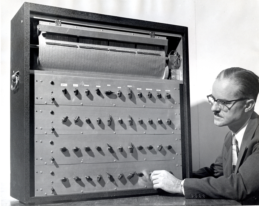
A 1942 photograph of the Electric Automatic Orchestra at the Hammond Sound Studio, Chicago with john Hanert at the controls. Showing (L) the ‘Time Sequence’ table and scanning carriage and (R) a bank of some of the vacuum tube tone generators. Photograph; Private collection of Douglas Jackson 2017.
Once the phonograph had supplanted radio and the pianola as the predominant format for music sales in the 1930s, attention turned to refining and accelerating the production and manufacture of records. 1Dolan, Brian. Inventing Entertainment: The Player Piano and the Origins of an American Music Industry. Rowman & Littlefield Publishers Inc 2009.Hammond Organ Inc’s chief Designer John M. Hanert – who was responsible for the design of the hugely successful tonewheel ‘Hammond Organ’ series as well as the vacuum tube based ‘Solovox’ and ‘Novachord’ instruments – was contemplating a self-contained device that could be used as a composition system, sound synthesiser and gramophone production tool:
“My invention relates generally to apparatus for production as sound or as a signal for recording purposes, without the employment of musicians in anyway whatsoever.” 2 John M Hanert US Patent 2,541,051 Apparatus for automatic production of music,Feb. 13, 1951.
The result of Hanert’s experiment was the Electric Automatic Orchestra; a large, room sized machine installed at the Hammond Instrument Inc. sound studios at 2915 North Western Ave Chicago Illinois. The basic function of the machine were divided into three parts; a composition ‘Time Sequence’ table where the composer could write musical notation into the machine, a synthesis module which created sounds from the notation, and an output – in this case a lacquer disc-lathe to cut master recordings.
Diagram illustrating the notation card template with pitch on the X axis and duration/position on the Y axis. The scanning head travelled along the Y axis. (US Patent 2,541,051A 1945)
The ‘Time Sequence’ section was an eighteen meter table – extendable to the amount of room-space available – covered with overlapping ‘record notation’ cards of approximately 28 X 30 cm. These cards could be drawn on with conductive graphite or aquadag marks representing musical information. Above the table travelled a wheeled electric-motor driven ‘scanning carriage’ equipped with multiple phosphor-bronze contact brushes. When the brushes made contact with the conductive graphite marks on the cards below, an electronic signal was generated that triggered the relevant musical reaction in the sound generating part of the instrument. (Hanert also provided an alternate photoelectric set of scanning heads which could replace the contact brushes.)
Hanert’s design enabled the composer to a create ‘perfect’ compositions by writing, erasing and re-writing the music on the ‘Time Sequence’ table – which could be done on or off-site or as required. Once this perfect composition had been achieved, the machine could make a final run and cut a master recording to disc to be used for mass production.3 Rhea, Tom. ‘The Hanert Synthesizer’ Electronic Perspectives, Contemporary Keyboard September 1979 p78.
The record notation cards were pre-printed with a grid like template and could be marked to represent individual note pitch – measured in quarter tones, envelope, timbre, vibrato, position in the bar and volume as well as overall instrument volume. The final tempo of the piece could be controlled by simply varying the speed of the rail driven scanning carriage as it travelled along the table or paused, reversed or ‘looped’ by control marks on the cards. The length of the table defined the length of the piece, which on this model, consisted of 39 cards giving a maximum playing length of 96 bars.4T.L.Rhea:”The Evolution of Electronic Musical Instruments in the United States” (diss., George Peabody College, Nashville, Tenn, 1972)
1942 Photograph of the electronic scanning heads of the Hanert Electrical Orchestra. Photo; Private collection of Douglas Jackson 2017.1942 Photograph of the electronic scanning heads of the Hanert Electrical Orchestra. Photo; Private collection of Douglas Jackson 2017.1942 Photograph of the electronic scanning heads of the Hanert Electrical Orchestra. Photo; Private collection Thom Rhea
The tones themselves were created by six separate banks of polyphonic vacuum tube generators similar in design to Hanert’s Novachord (USA, 1940). The instrument was also able to create percussive xylophone and drum sounds created by random (white noise) generators. Combinations of sounds could be defined on the notation cards allowing the composer to immediately switch instrument sounds as the piece progressed.
1942 Photograph of the tone generators of the Hanert Electrical Orchestra. Photo; Private collection of Douglas Jackson 2017.1942 Photograph of the tone generators of the Hanert Electrical Orchestra. Photo; Private collection of Douglas Jackson 2017.
Hanert’s instrument was unique in that for the first time a composer/producer could work in a nonlinear fashion: the composition cards could be erased or deleted simply by rubbing out the graphite mark or removing the card. Cards could be arranged in any order, enabling the composer to mix, transpose and reverse music themes and sounds, instrumentation could be changed at any point or applied to any written part of the composition. And, Hanert’s machine allowed the composer/producer the ability to monitor the results of the editing almost immediately. Hanert compared this facility to the practice of a visual artist:
The difficulties inherent in the orchestral production of a composition may be compared to those which would confront an artist who found it necessary in painting a picture to destroy the complete or partially complete picture he was painting every time he became dissatisfied with any slight detail of the picture. The painter is not subject to such stringent regulation but instead merely repaints such minor portion of the whole picture which does not represent the subject being painted sufficiently accurately to meet his artistic approval…In the method and apparatus of this invention the composer, arranger, or conductor has at his command means for controlling the quality of each note, its intensity, intensity envelope, the degree of accent, duration, and tempo without necessarily affecting any other note or tone of the composition.5US Patent 2,541,051A 1945,4.
Diagram from Hanert’s patent describing the sequence of tone filters and processors.
Despite its innovative qualities, the Electric Automatic Orchestra was never used commercially as Hanert had intended. In fact it seems that it was only ever used by Hanert himself and was not taken seriously by the Hammond company – who tended to humour Hanert’s ‘technical eccentricities’ in order to maintain his interest in more mundane but commercial designs. In addition to Hammond’s lukewarm support, the commercial failure of the project was also down to a combination of the synthetic nature of its sound, the inability of composers of the day to grasp the new musical paradigm the instrument offered plus the ever increasing capability and quality of recording technology– microphones, mixing desks, magnetic pick-ups, tape recorders – made the need for such a solution less pressing. The Electric Automatic Orchestra was sidelined and eventually mothballed by the Hammond company sometime during the 1950s.
Shortly after the disappearance of Hanert’s machine, David Sarnoff, chairman of RCA corporation, commissioned a self-contained commercial music production machine that could mathematically analyse and re-synthesise pop music.
“Composers don’t need to be able to play an instrument because our synthesizer will allow them to create any kind of music they want…Musicians aren’t required if you have our synthesizer.”6 David Sarnoff, chairman of RCA during the 1950s. Excerpt From: Vail, Mark. The Synthesizer, Oxford University Press, 2014, p271.
What became known of as the RCA Synthesiser (the first time ‘Synthesiser’ was used in a musical context) was installed at the Columbia–Princeton Electronic Music Center and directly referenced Hanert’s work (8). The machine used the same, though perhaps less flexible structure; a three stage process of music production – in this case a paper punch roll for composition, multiple banks of vacuum tubes for sound synthesis, and the same lacquer disc lathe for musical output.
Biography: John Marshall Hanert
John Marshall Hanert was born into a German-American family on 18th March 1909 in Milwaukee, Wisconsin. In 1932 Hanert was awarded a B.S. in Engineering and a BSE in Physics at The University of Michigan. An accomplished organist, Hanert had a special interest in electronic musical instruments and after graduation began working with Richard Ranger – inventor of the Rangertone Organ amongst other electronic musical devices – in New York on a Photo-Electrical musical instrument. In 1934 Hanert was appointed as the Head of Research at the Hammond Organ Inc in Chicago where he spent the rest of his life as the chief designer of all of Hammond’s instruments; Hanert became known as the musically untrained Laurens Hammond’s ‘Ears’.Hanert was the co-inventor on the first Hammond tone-wheel organ and inventor of the Solovox (1938) and Novachord (1939–42) one of the world’s first commercial synthesisers as well as many patents for vibrato and reverberation audio processors. Hanert continued working at the company After Laurens Hammond’s retirement in 1958 until he died on 23rd June 1962 at the age of 53 in a car accident near New Munster Wisconsin.7‘The Michigan Alumnus’ vol LXIX 1962-1963 page 63. Private collection of Douglas Jackson 2017.
References:
1
Dolan, Brian. Inventing Entertainment: The Player Piano and the Origins of an American Music Industry. Rowman & Littlefield Publishers Inc 2009.
2
John M Hanert US Patent 2,541,051 Apparatus for automatic production of music,Feb. 13, 1951.
The Clavioline was designed to be a light portable electronic keyboard aimed at pop musicians of the time and became one of the most popular electronic instruments during the fifties. The Clavioline was a monophonic, portable, battery powered keyboard instrument. The first version of the instrument appeared in 1947 and was originally designed by M. Constant. Martin in 1947 at his factory in Versailles, France. The Clavioline consisted of two units: the keyboard with the controllable sound unit and a carrying case box fitted with an with amplifier and speaker. By using an octave transposer switch the single oscillator could be set within a range of five octaves (six in the Bode version). The keyboard unit had 18 switches (22 in the Selmer version) for controlling timbre ( via a high pass filter and a low pass filter ), octave range and attack plus two controls for vibrato speed and intensity. The overall volume was controlled by a knee lever. Martin produced a duophonic model of the Clavioline in 1949 shaped like a small grand piano and featuring a 2 note polyphonic system, the duophonic model never went into production.
The Selmer Clavioline with stand, amplifier and loudspeaker cabinet
The Clavioline made brass and string sounds which were considered very natural at the time and was widely used throughout 1950’s and 60’s by pop musicians such as the Beatles, Joe Meek’s ‘the Tornadoes’ (on’Telstar’)and by experimental the jazz musician Sun Ra.
The Clavioline was licensed to various to various global manufacturers such as Selmer (UK) and Gibson (USA). An expanded concert version was produced in 1953 by René Seybold and Harald Bode, marketed by the Jörgensen Electronic Company of Düsseldorf, Germany. In the 1940’s Claviolines were also built into large dance-hall organs by the Belgian company Decap and Mortimer/Van Der Bosch.
The selmer Clavioline
The selmer Clavioline
Sources:
M.C.Martin: ‘L’apport de l’électronique à l’expression musicale’, Science et vie, ixxviii(1950),161
The Electronic Music Box was a synthesis and composition device designed and built as a personal project by Dr Earle.L.Kent while employed at the C.G.Conn Ltd Company, USA, to design electric organ circuits.1Margaret Downie Banks, Dynamic Research: Earle L. Kent and Conn’s Research Department, National Music Museum,The University of South Dakota. The Music Box was an analogue ‘beat frequency’ vacuum tube based synthesiser controlled by a punched paper strip device as used previously in the 1930’s by instruments such as Coupleaux’s Givelet and later, the RCA mkII and Siemens Synthesiser amongst others. The punch paper strip was a system similar to a ‘pianola’ paper reader and allowed the composer to produce musical sequences that were beyond the manual dexterity of the performer:
“The goals established for the music Box involved wider flexibility of performance than is possible in any conventional musical instrument. It was felt that it should not be confined to the usual limitations of manual keying. It should be capable of grater speed and wider combinations than are possible by manual or pedal dexterity, and it should not be limited to the equally tempered scales as are most keyed instruments. It was recognised that virtually any speed or combination could be obtained by keying with a perforated paper roll with the loss of some of the vital control usually exercised by a musician while making music and also with the loss of its conventional acceptance as a musical instrument. However, it was felt that a musician usually “records” his manual manipulation rather precisely in his brain before a concert by repetitive rehearsal and that the losses by recording this operation on paper would be exceeded by the gains”
Dr Earle.L.Kent
Dr Earle Kent at the C.G.Conn Ltd CompanyLabs c 1950
Although based on the established ‘beat frequency’/heterodyning principle, Kent’s instrument employed a more complex system of frequency changers to create a more interesting range of timbre and control over the shape of the note. The Music Box was designed to allow control off the ‘slurring’ of the note, formant filtering control and control of volume and depth and rate of tremolo. The Electronic Music Box was influential on the development of electronic musical instruments, Dr Kent was visited by Harry Olson who later adapted features of his RCA synthesiser to incorporate functions of the Music Box, but the Conn company chose not to exploit the commercial possibilities of the instrument.
Percy Grainger (L) and Earle Kent (R) with and ‘Dr Kent’s Electronic Music Box’ at Kent’s Research Engineering Department for the Conn Company, Elkhart, USA. image: Grainger Museum Archive, 99.6700.1
The Australian ‘Free Music’ composer Percy Grainger contacted Earle Kent shortly after Kent had completed his PhD at the University of Michigan. Grainger was looking for an instrument that would be suitable for his concept of free music:
“Play any pitch of any size, half, quarter or eighth tones, within the range of 7 voices, to be able to pass from pitch to pitch by way of a controlled glide as well as by leap, to play precisely controlled, complex irregular rhythms past the scope of human execution.”
Grainger visited Kent’s research department at the Conn Musical Instrument Company in Ekhart USA in 1951 to witness the Electronic Music Box which shared many features of Grainger’s somewhat crude constructions. However for undisclosed reasons, Grainger was unsatisfied with the Music Box and returned to his own Free Music experiments in Australia.2Grainger Museum Archive. https://omeka.cloud.unimelb.edu.au/grainger/
References
1
Margaret Downie Banks, Dynamic Research: Earle L. Kent and Conn’s Research Department, National Music Museum,The University of South Dakota.
2
Grainger Museum Archive. https://omeka.cloud.unimelb.edu.au/grainger/
‘This how the Composer-tron would look in your home – it may cost less than a piano’ Osmond Kendall’s ‘Composer-tron’ c1953 at the Film Board of Canada promoted as a domestic instrument (photo: Maclean’s, Canada’s National Magazine, June 11, 1955)
Developed as early as 1944 by Osmond ‘Ken’ Kendall, an electronic engineer at the National Film Board of Canada (NFBC) (and colleague of the animator Norman McLaren) the ‘Compositron’ and later the ‘Composer-Tron’ was an analogue synthesis and composition apparatus that utilised an innovative and unique control system. The Composer-Tron had a cathode ray tube input device that could ‘read’ patterns or shapes hand drawn on it’s surface with a grease pencil. The drawn shape could be defined as the timbre of the note or as the envelope shape of the sound, rhythmical sequences could be written by marking a cue sheet type strip of film:
“The Composer-tron is an electronic device that enables a composer or arranger of music to create his composition directly as he conceives it. The conventional aeries of intermediate steps—sheet music—musicians—musical instruments—room acoustics—microphones—are all eliminated. The composer produces his musical record for instant audition and he may do it in nearly the same time that he would take to compose and write a conventional musical score. The musical sounds he may use are limited only by his imagination since they may be like familiar musical instruments or completely unique.
The Composer-tron is not a musical instrument and it cannot he “played” in any sense at all. It’s designed to make records and it may be used for recording from a microphone. However, the Composer-tron is fitted with a new kind of electronic musical tone generator that may he adjusted by the composer to provide sound waves of any pitch, having overtones of any degree of complexity The tones may be made to match those of any known musical instrument or the wave structure may be set to tone qualities that could never be duplicated by any conceivable mechanical musical instrument whatever. The complex tones thus generated are shown to the composer in greatly enlarged form on a television tube screen. The composer then draws a design or pattern on a second screen. These designs may be original or they may be copied from the designs presented by recorded musical playings. Such designs often contain the elements of the “‘touch” of the musician and they can be made visible on the TV tube screen. This facility provides for the first timer means whereby the nuances of a musician’s touch may be superimposed on an electronic sound source. The design is transferred by methods similar to television. The resulting combined visible tone designs are converted into waves which are recorded and instantly auditioned over a loud-speaker.
The machine has a capacity for memorising op to 80-component instrument notes which may be finally recorded in any desired sequence. Other, facilities, such as a means for precisely timing the advent of each note, a means for developing chords directly (not necessarily derived from component notes), and a means for erasing faulty sections in a recording, etc., are all provided in the Composer-tron.”
Osmond Kendall quoted in ‘Canadian Film Technology, 1896-198’ (Gerald G. Graham, Ontario Film Institute University of Delaware Press, 1989)
” The compositron contains an oscilloscope to analyze sound patterns and a series of tapes or film on reels to record sound. Every sound has a pattern and when these patterns are played in a certain order on the films and then are played together, the required effect will be produced” Osmond Kendall at the Composer-tron/Compositron in Maclean’s Magazine, June 11, 1955
The purpose of the Composer-Tron, like that of the ‘Hanert Electrical Orchestra‘, was to provide a synthesis and composition tool that closed the gap between composer and performer allowing the composer to define all the aspects of the music in one session:
“At present, the composer writes his mental symphonies as black symbols on white paper. He has no way of knowing wether they’re just what he had in mind. Months or years may pass before he hears them played by a symphony orchestra. Not uncommonly he never hears his best work……with Kendal’s grease pencil, the composer can, in effect, draw the grooves in the record. Working with a Composert-Tron….he can walk out of his study with his recorded composition under his arm.”
Maclean’s Magazine, June 11, 1955
Osmond Kendall (L) and Louis Applebaum (R) at a photoshoot for Macleans Magazine analysing sound for the Composer-tron. “with the magic of electrons this inventive Canadian composes piano concertos and turns doodles into the sounds of an eighty-piece orchestra” (Maclean’s, Canada’s National Magazine, June 11, 1955)
The Composer-tron was designed primarily to provide synthesised soundtracks for films produced by the National Film Board of Canada during the post-war period of interest in hand-drawn audio soundtracks and experimental techniques (see the works of Norman McLaren and others). However with limited funding and scepticism from the NFBC the Composer-tron project ran into financial difficulties – An attempt during the early 1950’s to develop a commercial model aimed at amateur composers with funding from the Marconi Company proved unsuccessful. In desperation, Kendall and his mentor Louis Applebaum tried to keep the project alive by seeking funding from the Canadian military and the Bell Telephone Company which were ultimately also unsuccessful. The project was mothballed sometime in the late 1950’s.
Sources
‘The Art Of Electronic Music’ p46 Rhea,Tom.L. Edited by Darter,Tom & Greg Armbruster 1984 GPI Productions.
Alan Phillips, ‘Osmond Kendall’s Marvellous Music Machine’ Maclean’s Magazine, June 11, 1955. [p.54]. York University Archives, Louis Applebaum fonds 1979 -002/030.
‘Music in Canada: Capturing Landscape and Diversity’. Elaine Keillor. McGill-Queen’s Press – MQUP, 18 Mar 2008
‘Louis Applebaum: A Passion for Culture’. Walter Pitman. Dundurn, 1 Oct 2002
Louis Applebaum, letter to Arthur Irwin, Commissioner, NFB, December 6, 1950. York University Archives, Louis Applebaum fonds, 1979-002/022
‘Composertron’ Hugh Davies. The Grove Dictionary of Musical Instruments, 2nd edition, issue Published in print January 2001.
‘Canadian Film Technology, 1896-1986’. Gerald G. Graham, Ontario Film Institute. University of Delaware Press, 1989


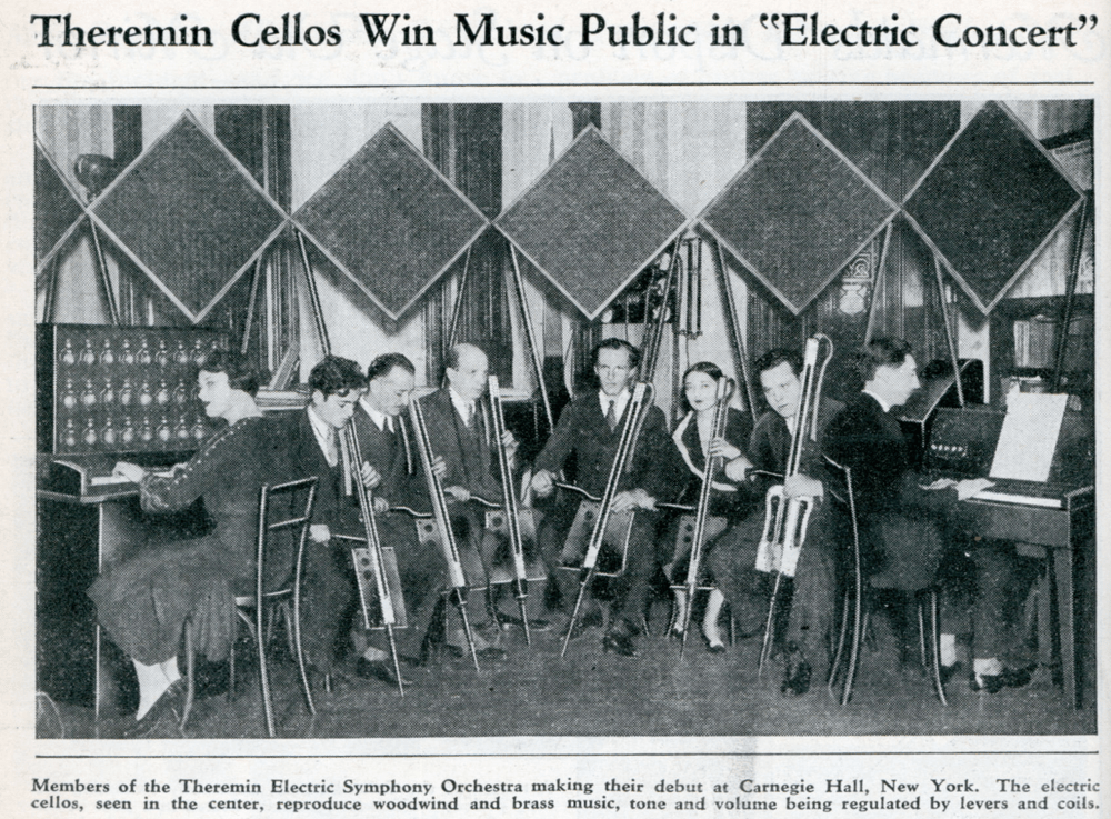


, where he presented different technical possibilities to combine music and color, music and gesture, music and tactile senses, music and smelts.")


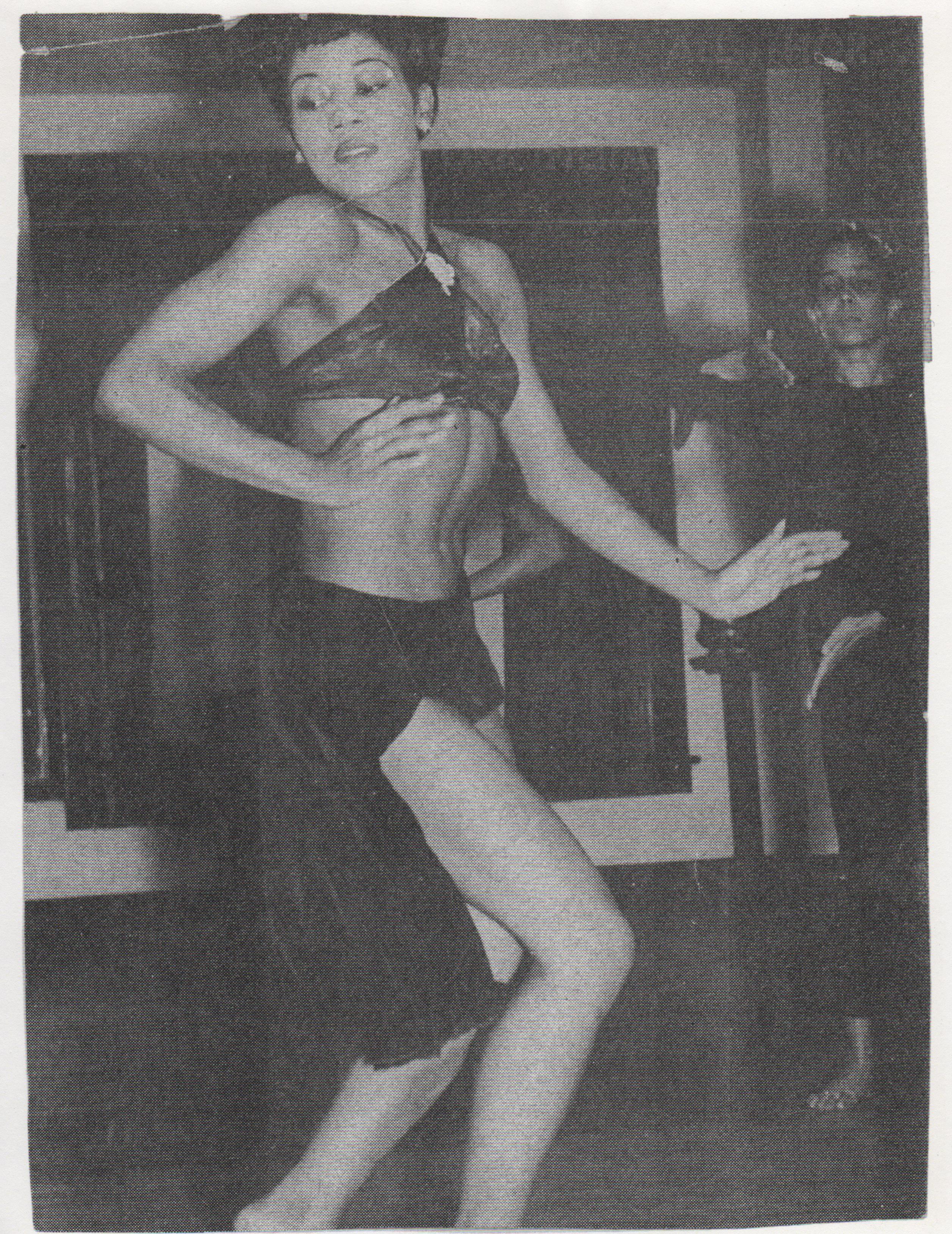


!["Electric Concerts" with the electroacoustic "orchestra of the future", 1932/1933 On the occasion of the 9th and 10th IFA in Berlin 1932 and 1933 for the first time found concerts with "Electric Music" instead. They played by the so-called "Orchestra of the future" all electroacoustic musical instruments then available. The "Elektischen concerts" made at the time an exceptional level of interest and broad support in the public, as the cooperating with private Theremingerät Erich Zitzmann-Zerini [second right] the engineer Gerhard Steinke told while gave him this original image. The orchestra consisted of two theremin instruments Trautonium [by Trautwein], Heller desk [of B. and P. Helberger Lertes], a neo-Bechstein grand piano [for suggestions of O. Vierling, S. Franco, W. Nernst and H . Driescher], Vierling piano [electro Acoustic piano by O. Vierling], electric violin, electric cello and Saraga generator [a light-electric device by W. Saraga, in principle, similar to the Theremingerät]. Photo: archive Gerhard Steinke](https://i0.wp.com/120years.net/wp-content/uploads/2013/09/Funkausstellung-mit-Elektronischer-Musik-for-web.jpg?resize=660%2C409)


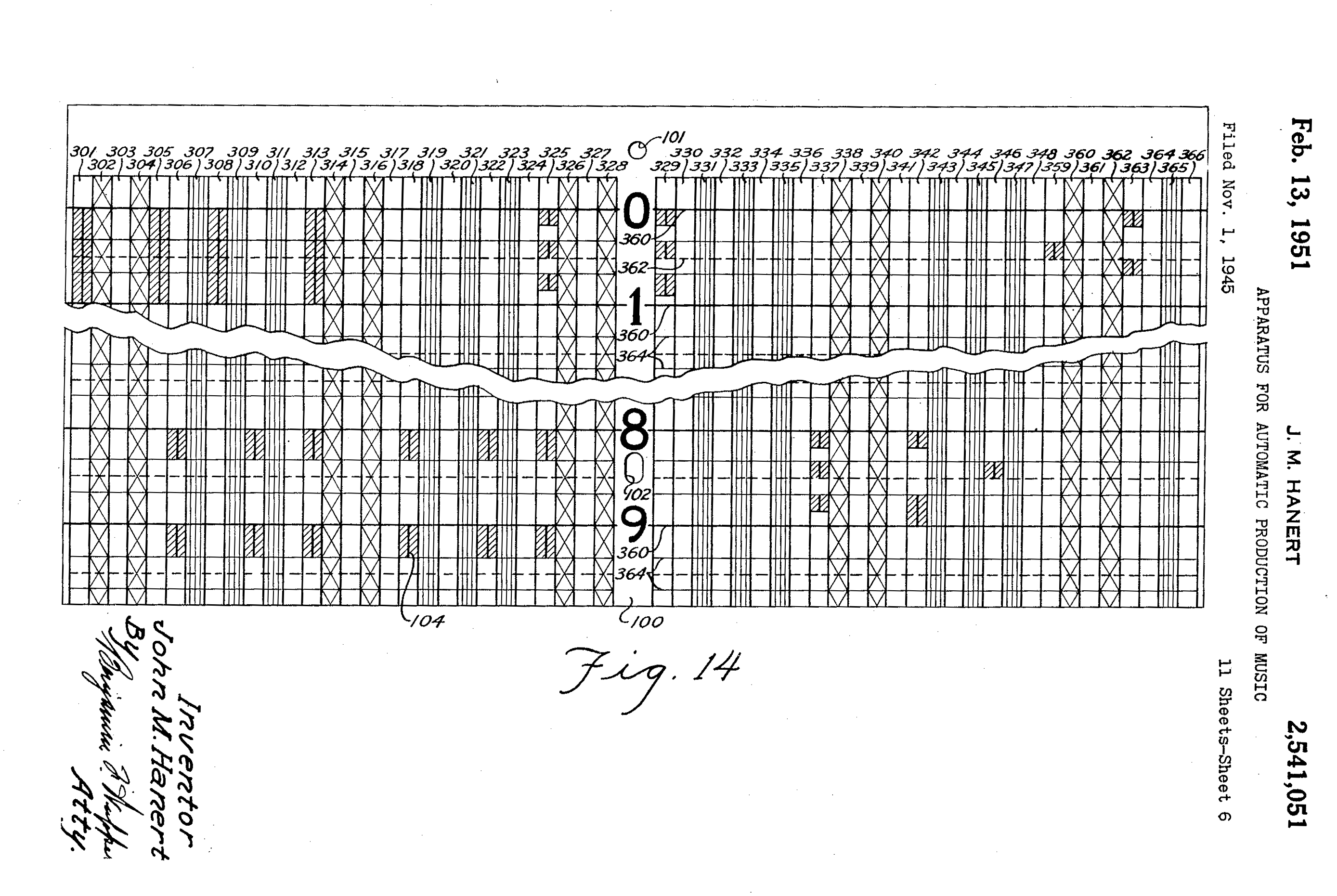


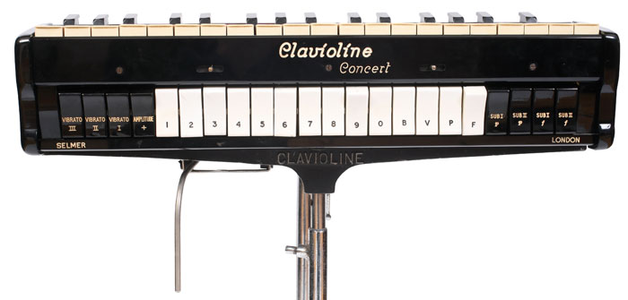


")