The ‘Rhythmicon’ Henry Cowell & Leon Termen. USA, 1930

Henry Cowell and the Rhythmicon
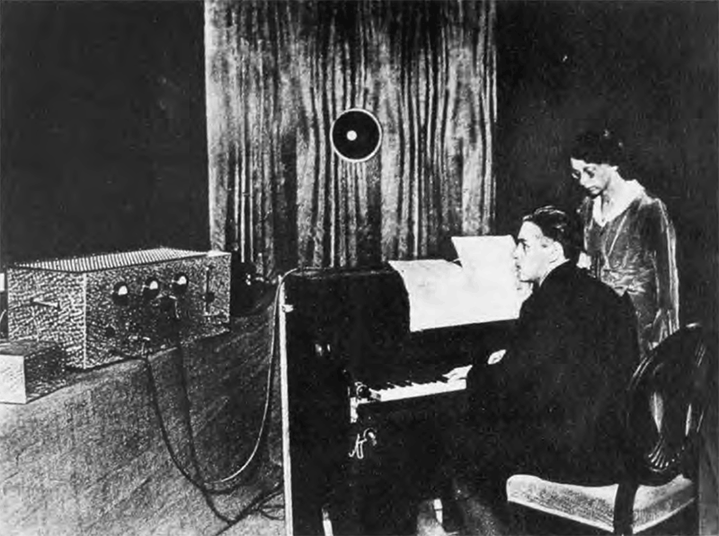
The composer Joseph Schillinger and the Rhythmicon. Image (c)

In 1916 the American Avant-Garde composer Henry Cowell was working with ideas of controlling cross rhythms and tonal sequences with a keyboard, he wrote several quartet type pieces that used combinations of rhythms and overtones that were not possible to play apart from using some kind of mechanical control- “un-performable by any known human agency and I thought of them as purely fanciful”(Henry Cowell) 1Cowell, H. . In 1930 Cowell introduced his idea to Leon Termen, the inventor of the Theremin, and commissioned him – for the fee of $200 –  to build a machine capable of transforming harmonic data into rhythmic data and vice versa.2 According to Mead “Even though Theremin was at the time receiving offers as high as $10,000 from Hollywood studios for work with his earlier instrument, the Theremin, he only charged Cowell $200 for the Rhythmicon because, according to Mrs Cowell, he always enjoyed Cowell and was glad to help him”  – Mead, Rita H,(1981) Henry Cowell’s New Music, 1925-1936 : the Society, the music editions, and the recordings, Ann Arbor, Mich. : UMI Research Press,188-9. 

“My part in its invention was to invent the idea that such a rhythmic instrument was a necessity to further rhythmic development, which has reached a limit more or less, in performance by hand, an needed the application of mechanical aid. The which the instrument was to accomplish and what rhythms it should do and the pitch it should have and the relation between the pitch and rhythms are my ideas. I also conceived that the principle of broken up light playing on a photo-electric cell would be the best means of making it practical. With this idea I went to Theremin who did the rest – he invented the method by which the light would be cut, did the electrical calculations and built the instrument.” Henry Cowell 3 Henly, H (1932) Music: New Futures for Rhythms, Argonaut, CX/2846 (May 20, 1932), 10.
“The rhythmic control possible in playing and imparting exactitudes in cross rhythms are bewildering to contemplate and the potentialities of the instrument should be multifarious… Mr. Cowell used his rythmicon to accompany a set of violin movements which he had written for the occasion…. The accompaniment was a strange complexity of rhythmical interweavings and cross currents of a cunning and precision as never before fell on the ears of man and the sound pattern was as uncanny as the motion… The write believes that the pure genius of Henry Cowell has put forward a principle which will strongly influence the face of all future music.4 Henly, H (1932) Music: New Futures for Rhythms, Argonaut, CX/2846 (May 20, 1932), 10. Homer Henly, May 20, 1932.
Rhythmicon Discs
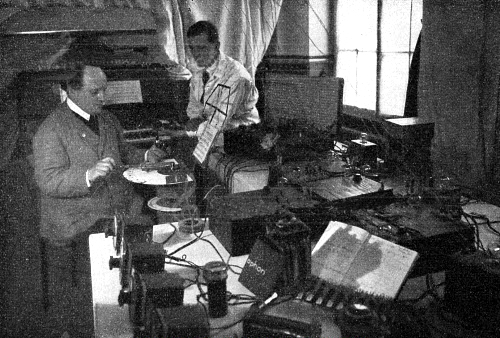
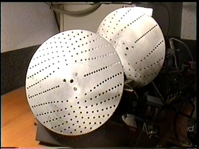
Optical rhythm discs of the Rhythmicon. Image (o)

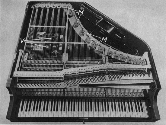
Termen and Cowell christened their machine the Rythmicon or Polyrhythmophone (or sometime the Theremin-Cowell Rythmicon) and it can be seen as the first electronic rhythm machine. The 17 key polyphonic keyboard produced a single note repeated in periodic rhythm for as long as it was held down, the rhythmic content being generated using a photo-electrical technique: rotating perforated disks interrupted light beams that triggered photo-electric cells which in turn generated a rhythmical electronic pulse. The keyboard was laid out in a non-standard fashion arranged in a regular sequence of black
and white – the lowest note produced a unit of rhythm; white keys produced even divisions of it; black keys produced odd-numbered divisions up to a fifteenth of that basic pulse.5Sachs, Joel,(2012), Henry Cowell: A Man Made of Music, Oxford University Press, Inc, 223. . The transposable keyboard was tuned to an unusual pitch, based on the rhythmic speed of the sequences and the basic pitch and tempo – essentially each separate rhythm had its own pitch which was combined into a polyrhythmic-melodic piece.

Henry Cowell playing the Rhythmicon c 1932. Image: (c) the Imogen Cunningham Trust

The instrument was first unveiled at The New School New York on January 19, 1932, with the assistance of Clara Reisenberg (the famed Theremin virtuoso Clara Rockmore) and with Lev termen who demonstrated his Theremin Cello and keyboard Harmonium, and later at the same location on March 10th where termen also demonstrated his dance-performance instrument, the Terpsitone where Clara Reisenberg’s movements controlled the instruments pitch. The Rhythmicon never lived up to Cowell’s musical ambitious expectations and generally received a negative reception from critics who, focussing on the instruments harmonic shortcomings, disregarded Cowell’s rhythmic-melodic ideas.6Sachs, Joel,(2012), Henry Cowell: A Man Made of Music, Oxford University Press, Inc, 225. .

The sound of the Rhythmicon, produced by an array of six vacuum tubes was characteristically thin and was often described as unimpressive: “The melodic possibilities of the instrument seem small, though its theoretical interest is high. The sound is like that of a reed organ.” 7 Mead, Rita H,(1981) Henry Cowell’s New Music, 1925-1936 : the Society, the music editions, and the recordings, Ann Arbor, Mich. : UMI Research Press,189.) or in another review by the music journalist Alfred Metzger in the San Francisco Chronicle (May, 1932) “like a cross between a grunt and a snort in the low ‘tones’ and like an Indian war whoop in the high tones”8 Metzger, A, (1932), Newest invention in music makes debut in SF, San Francisco Chronicle, May 16th 1932.

Cowell wrote two works for the Rythmicon; Rythmicana (renamed Concerto for Rhythmicon and Orchestra 1931 9 Mead, Rita H,(1981) Henry Cowell’s New Music, 1925-1936 : the Society, the music editions, and the recordings, Ann Arbor, Mich. : UMI Research Press,189.) and Music for Violin and Rythmicon (now lost, 1931 – a computer simulation of this work was reproduced in 1972). Cowell, however, discouraged by the instruments negative reception, eventually lost interest in the machine, transferring his interest to ethnic music and the machine was mothballed.

“In 1934, realizing that he [musicologist and financer of the Rhythmicon Nicolas Slonimsky] never could bring the instrument to Boston because, in those days of unstandardized electric service, the predominant DC current required a costly converter for the AC Rhythmicon, he offered it to Henry or the New School for half the original price. 108 In the end Slonimsky sold it for $90 to [US Composer] Joseph Schillinger, who used it in his teaching and eventually gave it to the Smithsonian. The second Rhythmicon was stored by Henry at Stanford, where it eventually fell apart and was scrapped.” 10Sachs, Joel,(2012), Henry Cowell: A Man Made of Music, Oxford University Press, Inc, 222. .

The remaining existing version of the Rhythmicon is a model created by Termen on his return to the USSR in the 1960s and resides at the Theremin Institute in Moscow (as of 2020).

The 1960s Rhythmicon at the Theremin Institute Moscow. Image: Theremin Institute/Andrei Smirnov

References:

  • 1
    Cowell, H. ↩︎
  • 2
    According to Mead “Even though Theremin was at the time receiving offers as high as $10,000 from Hollywood studios for work with his earlier instrument, the Theremin, he only charged Cowell $200 for the Rhythmicon because, according to Mrs Cowell, he always enjoyed Cowell and was glad to help him”  – Mead, Rita H,(1981) Henry Cowell’s New Music, 1925-1936 : the Society, the music editions, and the recordings, Ann Arbor, Mich. : UMI Research Press,188-9.  ↩︎
  • 3
    Henly, H (1932) Music: New Futures for Rhythms, Argonaut, CX/2846 (May 20, 1932), 10. ↩︎
  • 4
    Henly, H (1932) Music: New Futures for Rhythms, Argonaut, CX/2846 (May 20, 1932), 10. ↩︎
  • 5
    Sachs, Joel,(2012), Henry Cowell: A Man Made of Music, Oxford University Press, Inc, 223. ↩︎
  • 6
    Sachs, Joel,(2012), Henry Cowell: A Man Made of Music, Oxford University Press, Inc, 225. ↩︎
  • 7
    Mead, Rita H,(1981) Henry Cowell’s New Music, 1925-1936 : the Society, the music editions, and the recordings, Ann Arbor, Mich. : UMI Research Press,189. ↩︎
  • 8
    Metzger, A, (1932), Newest invention in music makes debut in SF, San Francisco Chronicle, May 16th 1932. ↩︎
  • 9
    Mead, Rita H,(1981) Henry Cowell’s New Music, 1925-1936 : the Society, the music editions, and the recordings, Ann Arbor, Mich. : UMI Research Press,189. ↩︎
  • 10
    Sachs, Joel,(2012), Henry Cowell: A Man Made of Music, Oxford University Press, Inc, 222. ↩︎

The ‘Terpsitone’, Leon Termen, USA & Russia,1932.

Termen’s Terpsitone 1936. Clara Rockmore, Theremin virtuoso dances with the Terpsitone at Carnegie Hall, March 10th, 1933. Image Popular Science 1933.

The Ether-wave Dance Platform later named the Terpsitone, named after the muse of dance Terpsichorè, was a movement controlled instrument using the same capacitance principles of the Theremin.1Sachs, Joel, (2012) Henry Cowell : a man made of music, New York : Oxford University Press, 224. The Terpsitone was designed built by Leon Termen for his wife the US dancer Lavinia Williams.2 Mattis, Olivia, (1989) Interview of Leon Theremin (Lev Sergeyevich Termen), Bourges, France, 16 June 1989, http://www.vasulka.org/, retrieved 21-01-202. The Terpsitone removed the control antenna of the Theremin and replaced it with a large metal sheet hidden under the floor. Movements of the dancer in the area above the sheet caused variations in pitch of the Terpsitone’s oscillators due to the capacitance of the dancer’s bodies. This instrument was used for several ‘exotic’ dance, music and light shows throughout the 1930’s. As Termen described it:

“This is a platform that a person dances on. When the dancer’s body is low, you hear the lowest pitch. When the dancer raises her body, the pitch also goes up. It’s also possible to dance without changing the sound. For instance, if the dancer raises one arm and lowers the other, there will be no change in pitch. But if the dancer raises both arms, then the pitch will go up. […] If the dancer goes more forward, it pets louder. When she steps back, the sound gets quieter. I had a Terpsitone dance studio in New York. I had many pupils dancing there.”3 Mattis, Olivia, (1989) Interview of Leon Theremin (Lev Sergeyevich Termen), Bourges, France, 16 June 1989, http://www.vasulka.org/, retrieved 21-01-202.

The Terpsitone at the Theremin Institute, Moscow. Image: Theremin Institute,/Andrey Smirnov.

Gimazutdinov describes the Terpsitone in the Prometheus journal:

“During his long and bright life, Leo Sergeyevich Termen made numerous discoveries and inventions. Among the different kind of brilliant inventions was the Terpsitone – which makes it possible for dancers to combine movement of body with music and light. Idea of the Terpsitone occurred to L.Termen at the beginning of the 20th century, probably, immediately after the creation of Thereminvox. But as opposed to the Thereminvox where the pitch of tone and loudness depends on the position of the hands of the musician, the Terpsitone frequency and amplitude of sound are determined by a change in the position of entire body of a dancer. The operating principle of the Terpsitone is very similar to the operating principle Thereminvox, based on obtaining audio beat-frequencies, formed by the interaction of high-frequency fluctuations of two oscillators. One has frequency rigidly fixed, while in the second is variable. In the second oscillator the frequency depends on a change in the distance between the capacitor plates of oscillatory circuit. One of the capacitor plates is an isolated, metallic plate placed on the floor of dancing hall, and second facing the body of the dancer. By moving through the space the dancer affects a change in the capacity of oscillatory circuit and, correspondingly, a change in the difference audio frequency. This signal is amplified and sent to the loudspeaker. Thus the motions of the dancer is converted into sound, which change synchronously with a change in the position of body. The possibility of adding automated colour is an additional special feature of the invention. The “visual sound display” is a panel with  lamps, painted in different colours where the lamps light up to the motion of the dancer, moreover lamps with the specific colour corresponds to each note. However, this is ensured partially mechanically.

The Terpsitone in the acoustic laboratory, Moscow, 1966 consists of:

1) the electronic-music block, which works on the principle of Thereminvox with heterodyning high frequencies, with the device for vibrato and by a change in the loudness of sounding loudspeaker

2) An  electrical capacitance dancing platform with the size of 2 X of 1,8 X of 0.2 meters with that placed under it along entire its length and width by the electrode, connected through the resonance involving system with one of the high-frequency generators of musical block;

3) A dynamic loud-speaker with control of intensity and timbre. A Range-tool for the performance of melody by the motions of arms, head and legs of the dancer who stands on the platform – 2 octaves. More low-pitched sounds correspond to the locked position of hands and housing of that dancing, high to a maximally opened position, with the large external overall sizes. This experimental device adapts for training the executors of this new form of choreographic- musical skill. Are developed also the electrical circuits of the additional devices:

3.1) movement of executor forward gives audio gain, and its presence in the background ceases sound by means of the electrical capacitance influence on the electrode, fastened on the rear wall of dancing platform

3.2) the invariability of the pitch of tone with the displacement of that dancing and the appearance of that corresponding to the position of the executor of the new height of sounding with the cessations of motion.

Executors: Heads by the laboratory of acoustics and sound recording – Yurchenko A.D, the supervisor of sector – Termen L.CH., engineer – Rudakov YE.A., engineer – Matveyev V.N., technician.”

4Gimazutdinov K.N. (1966) Termen’s “Terpsitone”, Kazan, NII – SCIENTIFIC RESEARCH INSTITUTE “Prometheus”.

References:

  • 1
    Sachs, Joel, (2012) Henry Cowell : a man made of music, New York : Oxford University Press, 224. ↩︎
  • 2
    Mattis, Olivia, (1989) Interview of Leon Theremin (Lev Sergeyevich Termen), Bourges, France, 16 June 1989, http://www.vasulka.org/, retrieved 21-01-202. ↩︎
  • 3
    Mattis, Olivia, (1989) Interview of Leon Theremin (Lev Sergeyevich Termen), Bourges, France, 16 June 1989, http://www.vasulka.org/, retrieved 21-01-202. ↩︎
  • 4
    Gimazutdinov K.N. (1966) Termen’s “Terpsitone”, Kazan, NII – SCIENTIFIC RESEARCH INSTITUTE “Prometheus”. ↩︎

The ‘Sonar’, Nikolai Anan’yev , Russia,1933.

The Sonar 1933. Image: Sound in Z, Experiments in Sound and Electronic Music in Early 20th Century Russia, Koenig, 95.

The Sonar was a monophonic vacuum tube instrument developed by Nikolai Anan’yev at the GIMN Acoustic Laboratory in the USSR from 1930. The Sonar used the same  heterodyning principles of Termen’s Thereminvox but with the addition of a fretted fingerboard made from a long, narrow conductive strip to vary the pitch of the oscillator – a technology used in several other instruments of the ear including the Trautonium, Hellertion and Ondes Martenot. Anan’yev considered the Sonar to be an improvement of the Thereminvox and the addition of a fingerboard made the Sonar more popular (at the time in the early Soviet period) with musicians due to it’s familiarity and playability.1Smirnov, Andrey, (2013) Sound in Z, Experiments in Sound and Electronic Music in Early 20th Century Russia, Koenig, 95.

Later versions of the instrument had a timbre and volume pedal control that meant the Sonar was said to have been able to reproduce violin like timbres – Anan’yev competed for realism with a well-known violinist and the audience was said to favour the Sonar– as well as simple speech phrases such as “mama”, “papa” as well as conventional instrumental sounds and became known for it’s use in ‘proletarian’ outdoor events. In the 1930s a course for Sonar performers was established at the Saratov Conservatory and Anan’yev  gave over six hundred concerts to around five hundred thousand people with the Sonar during his lifetime.2 Davies, Hugh & Smirnov, Andrey (2014), The Sonar, The Grove dictionary of musical instruments, New York : Oxford University Press, 480.


References:

  • 1
    Smirnov, Andrey, (2013) Sound in Z, Experiments in Sound and Electronic Music in Early 20th Century Russia, Koenig, 95. ↩︎
  • 2
    Davies, Hugh & Smirnov, Andrey (2014), The Sonar, The Grove dictionary of musical instruments, New York : Oxford University Press, 480. ↩︎

The ‘Saraga-Generator’, Wolja Saraga, Germany,1931.

The Saraga Generator
One of the sound generating devices built by Wolja Saraga at the HHI. Photo; Saraga family archives

Wolja Saraga was a research doctoral student and then lecturer from around 1929 until 1936 at the newly formed (1928) Heinrich-Hertz Institut Für Schwingungsforschung (Heinrich hertz Institute for Frequency Research or HHI for short) based on Franklin Str 1, Charlottenburg, Berlin, Germany. The HHI was tasked with research into all forms of frequency research – communications, radio, physics, acoustics and electronic musical instruments. Under the direction of Prof Gustav Leithäuser the HHI became the international center for the development of electronic musical instruments through the work of figures such as Fritz Sennheiser,  Oskar Vierling Harald Bode , Winston KockFriedrich Trautwein and Wolja Saraga.

The Heinrich-Hertz-Institut für Schwingungsforschung, Charlottenburg, Berlin. Image: Architekturmuseum der Technischen Universität Berlin Inv. Nr. F 8108.

In 1932 Saraga began to investigate the opportunities and practicalities of musical sound production via three main approaches: optical sound synthesis, direct sound generation through ‘direct discharge’ and by using a voltage controlled tungsten arc-lamp.1Saraga, Wolja, (1932), Technischer Bericht Nr. 55,99, 100, Heinrich-Hertz-Institut für Schwingungsforschung, HHI Archives. The name Saraga-Generator has has become used for his more well-known photo-electrical instrument but probably applies better to his ‘direct discharge’ instrument that used a high voltage power generator to create spark-gap transmissions of sound waves. In this text it applies to all of his electronic musical experiments.

Saraga’s experiments with direct sound generation at the HHI  circa1930. Image: Funkbastler, H24, 1930, 409-10.

The Direkte elektrische Schallerzeugung or Direct Electrical Generator created a musical tone through direct stimulation of the air without loudspeakers – a method similar to Simon and Duddel’s early Singing Arc experiments of 1899. The result would have been at quite a high volume or, as Saraga put it “The desired kinetic effect is not negligible”. 2Saraga, Wolja, (1932), Technischer Bericht Nr. 55, 25 Jan 1932, Heinrich-Hertz-Institut für Schwingungsforschung, HHI Archives. The technique is explained in Saturday Review (1952): “The effect takes advantage of several physical principles:[5] First, ionization of a gas creates a highly conductive plasma, which responds to alternating electric and magnetic fields. Second, this low-density plasma has a negligibly small mass. Thus, the air remains mechanically coupled with the essentially massless plasma, allowing it to radiate a nearly ideal reproduction of the sound source when the electric or magnetic field is modulated with the audio signal.” 3 Villchur, Edgar, (1952) A New Speaker Principle, Saturday Review, 1952 Sep 27, 60-61.

Writing in Funkbastler Magazine, Saraga describes the sound of the instrument:

“The high-frequency glow arc also works with low background noise. Sometimes the presence of the counter electrode is also the cause of disturbing side effects. The air between the plates can oscillate itself and the acoustic change circumstances. Special forms of the counter electrode will probably prove to be particularly favourable. If you listen to the performances of the peak discharge, you will particularly notice the good reproduction of the high frequencies; the hissing sounds are very natural. The favourable acoustic radiation of the lower frequencies seems to be much more difficult, as the reproduction generally sounds a bit thin.4Saraga, Wolja, (1930) Schallerzeugung durch Hochfrequenzentladungen, Funkbastler, Heft 24, 409-10.

Saraga probably abandoned research in direct transmission for this reason – the low frequency reproduction was poor and because of the impracticalities of the approach: the amount of energy required and potentially hazardous by products produced by the ionisation process. 

The second approach Musikinstrument mit Wolframbogenlampe or Music Instrument with Wolfram Bow Lamp used used a tungsten arc-lamp connected to a loudspeaker without an amplifier which produced “very high volumes”. The tone of the lamp was modulated using a resistance manual; probably a metal strip touched by the player. 5Saraga, Wolja, (1932), Technischer Bericht Nr. 100, 13th September 1932, Heinrich-Hertz-Institut für Schwingungsforschung, HHI Archives.

Saraga’s photo-electrically controlled instrument the Elektrisches Photozellenmusikinstrument described in his 1932 HHI report, was a monophonic device that consisted of an audio oscillator controlled by movements of the performer’s hand between a low voltage neon lamp and a narrow V-shaped slit in the lid of a box. The white painted interior of the box had a photocell mounted on it positioned so that direct light would not reach it. The range of the instrument was about four octaves. Articulation and loudness were controlled by a switch, held in the performer’s other hand, and a volume pedal. 6Davies, Hugh (1984), Saraga-Generator, Grove Dictionary of Musical Instruments, Oxford University Press, 383. Saraga’s photo-cell instrument was patented in 1932 and demonstrated at the Berlin Radio Exhibition (IFA – Internationale Funkaustellung, Berlin) alongside the Orchester der Zukunft (the all-electric Orchestra of the Future) in the same year. Saraga described the timbral quality of the basic instrument as poor but one that could be easily rectified using the same type of format filters as Trautwein’s Trautonium7Saraga, Wolja, (1932) Ein Neues Elektrisches MusikInstrument, Funkbastler, Heft 10, 433-5.

"Electric Concerts" with the electroacoustic "orchestra of the future", 1932/1933 On the occasion of the 9th and 10th IFA in Berlin 1932 and 1933 for the first time found concerts with "Electric Music" instead. They played by the so-called "Orchestra of the future" all electroacoustic musical instruments then available. The "Elektischen concerts" made at the time an exceptional level of interest and broad support in the public, as the cooperating with private Theremingerät Erich Zitzmann-Zerini [second right] the engineer Gerhard Steinke told while gave him this original image. The orchestra consisted of two theremin instruments Trautonium [by Trautwein], Heller desk [of B. and P. Helberger Lertes], a neo-Bechstein grand piano [for suggestions of O. Vierling, S. Franco, W. Nernst and H . Driescher], Vierling piano [electro Acoustic piano by O. Vierling], electric violin, electric cello and Saraga generator [a light-electric device by W. Saraga, in principle, similar to the Theremingerät]. Photo: archive Gerhard Steinke
A concert by the electroacoustic “Orchestra of the Future” at the 9th and 10th IFA in Berlin 1932. Consisting of: (L-R) Bruno Hellberger playing his Hellertion, unknown playing the Electric Cello, Oskar Sala playing the Volkstruatonium, unknown playing the Neo Bechstein Electric Piano, Oskar Vierling playing the Electrochord, unknown playing the ‘Electric Violin’, unknown playing the ‘unknown instrument’,  Erich Zitzmann-Zerini with the Theremin, Unknown playing the Volkstrautonium. Saraga (not in the photograph) gave lectures on electronic music and demonstrations of his photo-electric instrument after each performance. Photo: archive Gerhard Steinke.
Saraga escaped Germany in 1936 (Bringing with him a Volkstrautonium purchased as a promotional model from Telefunken – which was confiscated by German authorities at the border) and eventually found employment in Orpington, Kent, UK. 8Interview with Esther Saraga, London 2015 In May 1946, Saraga founded the Electronic Music Group at the Northern Polytechnic (Holloway Rd, London) and tried to renew interest in his photo-electric instrument with public demonstrations of its capabilities and searched for commercial applications for the instrument including film soundtrack music and musical therapy for blind war veterans.

Saraga describes his instrument in an article in the Electronic Engineering journal, July 1945:

Basic diagram showing the box light-receiving device. Image: Electronic Engineering, July1945, 601

“A photo-electric cell is used as playing manual for controlling the pitch, the amount of light falling on this cell determining the frequency of the oscillation produced.* Thus the player can play on this instrument by varying the amount of light falling on the cell by moving his hand be- tween the cell and a source of light. This playing technique is in some aspects similar to that employed in Theremin’s instrument ; but there are some important differences which will be discussed, and it is hoped that the new playing technique will provide players and composers with new, hitherto unknown or technically im- possible, methods of expression.

The loudness of the tone produced can be controlled by means of a pedal which actuates a variable resistance or potentiometer. In a more elaborate form of the instrument it is intended to control the loudness by varying the amount of light falling on a second photo -electric cell. It is expected that this method of loudness control will be useful also in connection with other electronic musical instruments. For starting and stopping the tone the player uses a switch held in one hand which opens or closes the loud- speaker circuit. This switch is necessary because the loudness control by means of a pedal is rather slow. Instead of using a switch the player can close the- loudspeaker circuit by touching two metal contacts with his hand as a conducting link.” 9Saraga, W, (1945), An Electronic .Musical Instrument With a Photo -Electric Cell as Playing Manual, Electronic Engineering, 601.

Saraga argued that his instrument was superior to Termen’s Thereminvox in that it was easier and more natural to play:

“practical experience with Theremin’s instrument shows that its playing technique, while relieving the player from the resistance and inertia of the instrument, increases the resistance and inertia of his own hand because the hand has to be moved freely in the air for long periods with- out any physical support and without any visible indication of the correct positioning of the hand. Moreover, the pitch produced depends not only on the position of the hand but, to a smaller degree, also on the position of the whole body. Furthermore, the character of the electrostatic field of the rod in which the player moves his hand is such that it is very difficult to produce a linear pitch scale, i.e., to make the pitch proportional to the distance of the hand from the rod. The object of the new instrument […] is to eliminate these disadvantages of Theremin’s instrument. For this purpose the use of a photoelectric cell as -playing manual for determining the pitch or the loudness of the musical tones seems to be particularly convenient, because the geometrical relations of light beams’ and light and shadow which determine the amount of light falling on the cell when the hand of the player is in a certain position are much simpler, and much easier to control, than the geometrical relations of electrostatic fields which determine the hand capacitance in a certain position of the hand.10Saraga, W, (1945), An Electronic .Musical Instrument With a Photo -Electric Cell as Playing Manual, Electronic Engineering, 601.

Wolja Saraga working on the 'Saraga Generator' at the HHI, Berlin in 1932
Wolja Saraga working with a tungsten arc lamp for sound generation at the HHI, Berlin in 1932. Image: Saraga family archives.
Wolja Saraga. Berlin, 1930s
Wolja Saraga. Berlin, 1930s. Image: Saraga family archives.
Wolja Saraga working at the HHI, Berlin 1932. (Photo; TU Archives, Berlin)

Wolja Saraga: Biographical Notes

Wolja Saraga was a German Jewish Physicist, born in Berlin, Germany on 03-09-1908  to a Romanian father and a Russian mother. He studied telecommunications at the Heinrich Hertz Institute (Heinrich-Hertz Institut Für Schwingungsforschung or ‘HHI’) at the Technical University, Berlin under Prof Gustav Leithäuser. Saraga became a research assistant at the HHI and later  a lecturer from 1929-1933. He also studied physics and mathematics at the Humboldt University of Berlin, where he was awarded a Dr. phil. in physics in 1935.

saraga_presse_kart
Wolja Saraga’s ticket for the 1936 ‘Great-German Radio Exhibition’ (image; Saraga Family Archive 2016)

During his time in Berlin, Saraga was very energetic in promoting the potential of electronic music; He wrote numerous articles for journals and magazines on the subject of acoustics and audio technology and made several public presentations and demonstrations of electronic instruments including Theremins, Trautoniums and his own Saraga Generator. Saraga was also present playing the Saraga Generator at the 1932/3 International Funkaustellung (IFA) where the first ever electronic musical orchestra performed  – Das Orchester der Zukunft.

It became clear to Saraga in 1935-6 that as a Jewish scientist he would have no future in the new National Socialist German Reich and began to apply to leave the country, first of all to Switzerland and then to the UK. Saraga finally left Berlin in 1938 at the age of 29. he was initially held for six months on the Isle Of Man Hutchinson Camp as a German internee but was given a position working for the Telephone Manufacturing Company (or ‘TMC’) in St Mary’s Cray, Kent where, despite his unhappiness at his employers lack of interest in research, he remained until 1958.

A press card for a presentation by W.Saraga entitled 'Electronic Music'
A press card for a presentation by W.Saraga entitled ‘Electric Music – a presentation and musical demonstration of the Trautonium’. Berlin 1933. (Photo; Saraga Family Archive 2016)

Saraga then joined The Associated Electrical Industries Research Laboratory in Blackheath, London as a Research Scientist and Group Leader where he specialised in telephony filter design. In 1962, Saraga’s key contributions were recognised by the award of the Fellowship of the Institute of Electrical and Electronics Engineers, ‘for contributions to network theory and its application in communications’. In 1972, Saraga moved full time to Imperial College, London where he became a postgraduate lecturer and researcher in network theory and mathematics and wrote a number of books and filed several patents on network theory and telephony. Wolja Saraga died in London on Feb 15 1980.11Scanla, J,O,(1980) Obituary of Wolja Saraga, CIRCUIT THEORY AND APPLICATIONS, VOL. 8, 341.   , 12 (1980) Obituary of Wolja Saraga,  IEEPROC, Vol. 128, Pt. G, No. 4, AUGUST 1981. 13 Crab, Simon, (2015) Interview with Esther Saraga, london 2015.


References:

  • 1
    Saraga, Wolja, (1932), Technischer Bericht Nr. 55,99, 100, Heinrich-Hertz-Institut für Schwingungsforschung, HHI Archives. ↩︎
  • 2
    Saraga, Wolja, (1932), Technischer Bericht Nr. 55, 25 Jan 1932, Heinrich-Hertz-Institut für Schwingungsforschung, HHI Archives. ↩︎
  • 3
    Villchur, Edgar, (1952) A New Speaker Principle, Saturday Review, 1952 Sep 27, 60-61. ↩︎
  • 4
    Saraga, Wolja, (1930) Schallerzeugung durch Hochfrequenzentladungen, Funkbastler, Heft 24, 409-10. ↩︎
  • 5
    Saraga, Wolja, (1932), Technischer Bericht Nr. 100, 13th September 1932, Heinrich-Hertz-Institut für Schwingungsforschung, HHI Archives. ↩︎
  • 6
    Davies, Hugh (1984), Saraga-Generator, Grove Dictionary of Musical Instruments, Oxford University Press, 383. ↩︎
  • 7
    Saraga, Wolja, (1932) Ein Neues Elektrisches MusikInstrument, Funkbastler, Heft 10, 433-5. ↩︎
  • 8
    Interview with Esther Saraga, London 2015 ↩︎
  • 9
    Saraga, W, (1945), An Electronic .Musical Instrument With a Photo -Electric Cell as Playing Manual, Electronic Engineering, 601. ↩︎
  • 10
    Saraga, W, (1945), An Electronic .Musical Instrument With a Photo -Electric Cell as Playing Manual, Electronic Engineering, 601. ↩︎
  • 11
    Scanla, J,O,(1980) Obituary of Wolja Saraga, CIRCUIT THEORY AND APPLICATIONS, VOL. 8, 341.    ↩︎
  • 12
    (1980) Obituary of Wolja Saraga,  IEEPROC, Vol. 128, Pt. G, No. 4, AUGUST 1981. ↩︎
  • 13
    Crab, Simon, (2015) Interview with Esther Saraga, london 2015. ↩︎

The “Ekvodin”, Andrei Volodin , Soviet Union, 1931

Designed and built by the Russian inventor Andrei Volodin (1914-1981) the Ekvodin was a sophisticated and versatile electronic keyboard instrument. The instrument was unique at the time in allowing the player a high level of control over the timbre and shape of the sound. Apart from the standard keyboard manual the player was given extra control with various knee levers, sliders and foot pedals. The player could add vibrato effects to the note by manipulating the pressure sensitive keyboard directly. The instrument was also one of the first instruments to include what would become a standard feature in much later synthesisers, a bank of preset sounds which was said to accurately imitate musical instruments of the symphony orchestra including percussion. Volodin continued developing the instrument throughout the 1940s which culminated in a commercial model in the 1950s. However Volodin’s instrument was at the mercy of the Soviet Government who decided to stop funding the project in the mid 1960s after only twelve of the instruments were sold. Volodin continued research into musical acoustics and teaching at the Moscow State Conservatory as well as privately developing a polyphonic version of the Ekvodin and other electronic instruments, none of which were ever built.

EKVODIN is a professional musical instrument intended for universal use in various ensembles and orchestras and for solo performances including concerts with the accompaniment of piano and other instruments. The EKVODIN is suitable for different musical genres.The sound is produced in the EKVODIN on purely electrical principle. The instrument is noted for wide variety and brightness of timbres, broad range and high limit) power of the sound, and also for rational and highly-developed system of reproduction means (vibrating keyboard, loudness pedals, portamento, etc.). This ensures expressiveness and accuracy of performance. The profession of a piano player is closest to that of a man playing the EKVODIN. This similarity, however, does not determine the application of the EKVODIN which is, first of all, an ensemble and orchestra instrument.The EKVODIN comes in two design versions : one-voice and two-voice versions. A thoroughly developed system of timbres, varied with the aid of a special switch (and also depending upon the methods of performance), makes it possible to obtain an expressive and pleasant sound. The EKVODIN imitates quite fully the sound of symphonic orchestra instruments (bow, wood and brass groups, as well as certain percussion and pizzicato instruments) and also folk instruments. The EKVODIN allows to obtain sound personality in new timbres of modern style. The instrument can be used in mixed ensembles and orchestras for supporting and emphasizing different groups of solo parts performed on the usual (mostly string and brass) instruments, when their natural power is not quite sufficient for overruling the orchestra and for creation of new sounds. In incomplete orchestras and ensembles the EKVODIN can handle practically any part (the two-voice will handle two parts) of the bow, wood or brass groups. A special ensemble consisting of EKVODINS allows to obtain, for a very small number of instruments (sextet or octet), a multifarious, fluent and high – power sound in original and common timbres.Both design versions of the instrument come in semi-stationary (dismountable-transportable) construction and high-class finish. The extension loudspeaker unit, supplied with the instrument, can be located independently up to a distance of 5 m. The loudspeaker unit is installed depending upon the location of listeners. When carried or transported from place to place, the instrument is packed in two units of suitcase type. For operation the instrument is connected to alternating current mains (127 or 220 V).

The EKVODIN is not sensitive to fluctuations of the mains voltage. The one-voice version weighs about 35 kg, and its power consumption does not exceed 90 VA. The output power of the sound channel reaches 10 V. The two-voice version weighs about 65 kg, and its power consumption does not exceed 200 VA. The output power is up to 10 Win each channel, the timbre setting being independent for each voice. To double the. power of solo parts and timbre effects the voices can merge in unison, octave and two octaves.

Details from the Moscow Theremin Centre

Sources:

Theremin Centre, Moscow. interview with A.Smirnov by Simon Crab
Theremin centre website: http://theremin.ru/archive/volodin0.htm
Volodin, A. “Generation of sounds controlled by the force of the blow on the keys of electronic musical instruments (Electropiano),” Invention certificate, No. 66, USSR Cl. 154 (1946).
Volodin, A. “Acoustical-psychological aspects of the evaluation of musical sounds,” in Proc. of the 7th USSR Acoustical Conference (L., 1971).
Volodin, A. “Electrical synthesis of musical sounds as a basis for research on perception,” Voprosi psychologii, No. 6, p. 54-69 (1971).
Volodin, A. “Multifunctionality of the formants of musical sounds,” in Proc. of the 8th USSR Acoustical Conference (M., 1973).
Volodin, A. “Perception of vibrato in musical sounds,” in New research in psychology and age physiology, No. 2 (M., 1972).
Volodin, A. “Psychological aspects of the perception of musical sounds,” Candidate dissertation (M., 1972).
Volodin, A. “Perception of vibrato in musical sounds,” in New research in psychology, p. 3-5 (M., 1974).
Volodin, A. “The role of harmonic spectrum in perception of pitch and timbre,” in Musical Art and Science, issue 1, p. 11 (M., 1970).

The ‘Variophone’ Yevgeny Sholpo. Russia, 1932

Sholpo's Variophone
Sholpo’s Variophone 1949 Model

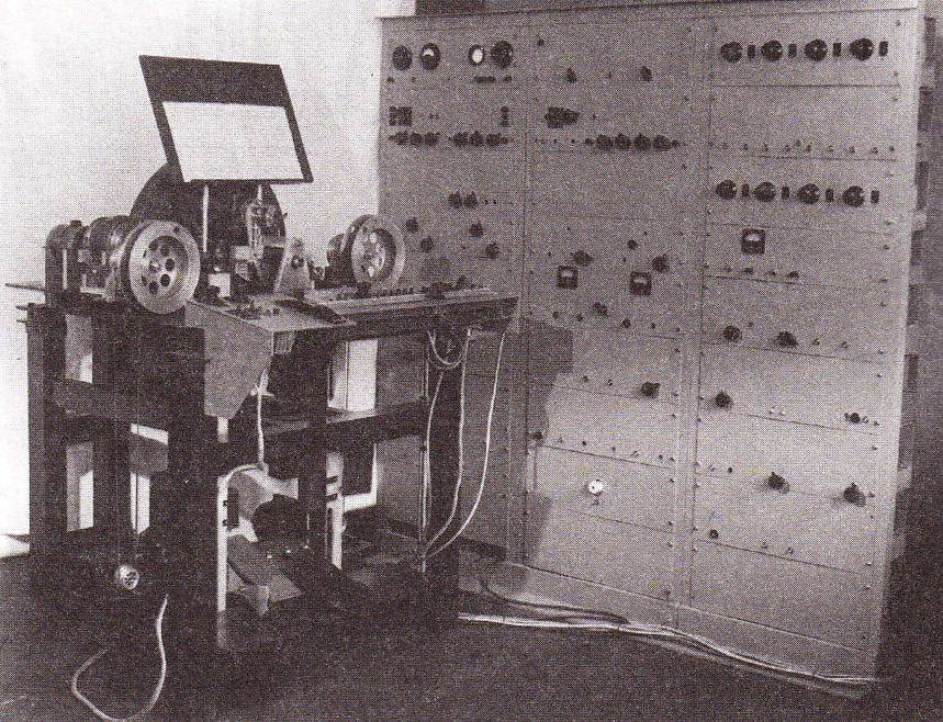
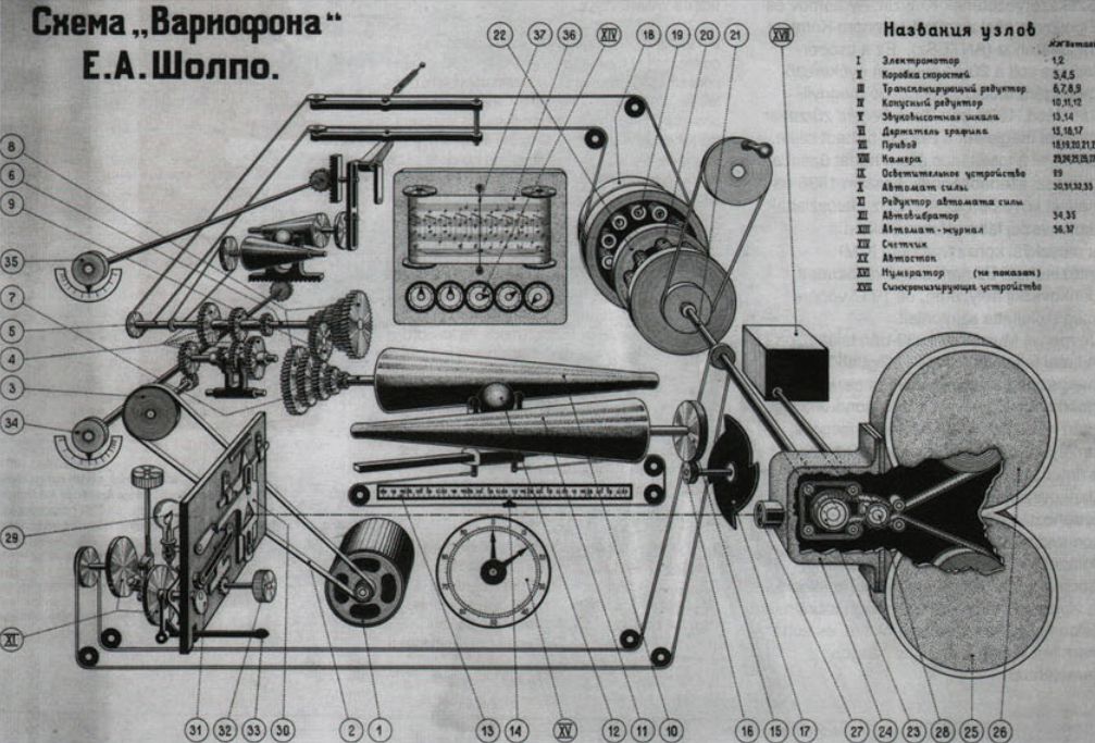
Developed in the Soviet Union in 1932 by Yevgeny Alexandrovitch Sholpo and Georgy Rimsky-Korsakov at the Central Laboratory of Wire Communication in Leningrad after several years research into performer-less music; the Variophone was an photo-electrical electronic instrument. The particular method used by the Variophone was a type of optical audio recording designed to allow the composition of lengthy polyphonic pieces of music. This was achieved by cutting sound waves into cardboard discs rotating in synch with a 35 mm movie film. This was then re-filmed and played back on a normal movie projector that and amplified through a speaker. In a simple ‘overdubbing’ process the process could be repeated to create multiple layered tones.

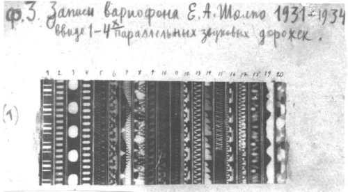
Soundtracks were able to contain up to twelve voices, recorded as tiny parallel tracks inside the normal soundtrack film area. By 1931 with the help of Rimsky-korsakov, Sholpo produced soundtrack to the film ‘The Year 1905 in Bourgeoisie Satire’ and again in 1932 a synthesised soundtrack for ‘A Symphony of Peace’ and many other soundtracks for films and cartoons throughout the Thirties and Forties. At the end of the long 1941 Siege of Leningrad, the Variophon was destroyed during a missile attack. After World War Two, Evgeny Sholpo became the director of the new ‘Scientific‐Research Laboratory for Graphical Sound’ with Boris Yankovsky at the State Research Institute for Sound Recording, in Leningrad..

Early version of the Variophone

The fourth and final version of Variophone was never finished, despite promising experiments in musical intonation and the temporal characteristics of live musical performance. The laboratory was moved to Moscow and Sholpo was removed from his position as director. In 1951, after a long illness, Evgeny Sholpo died and his laboratory was closed.Archive material from the Variophone was recently transferred in 2007 to the Theremin Center.

Variophone diagram
Variophone diagram
Tone discs
Tone discs
Sholpo's Variophone
Sholpo’s Variophone 1949 Model

In Russia from the 1920’s until the  1970’s there was a particular interest in photo-electrical synthesis; probably due to the influence of the theories and writings of Alexander Scriabin who proposed a uniting theory of sound and light.  The first ‘drawn’ soundtrack ever created by the avant-garde composer Arseny Avraamov who produced film soundtracks created by photographing series of drawings such as “Plan Velikikh Rabot” (Plan of great works) and “Kem Bit” (‘who to be’) in 1930. Boris Yankovsky was developing a more complex spectral analysis, decomposition and re-synthesis technique, resembling the recent computer music techniques of cross synthesis and the phase vocoder. This process was also seen as a way of liberating the composer from the practical restrictions of instrumentation and musicians:

While most inventors of electronic musical instruments were developing tools for performers, the majority of methods and instruments based on Graphical Sound techniques were created for composers. Similar to modern computer music techniques, the composer could produce the final synthesised soundtrack without need for any performers or intermediates.”
Smirnov, Andrey, 2011 “Graphical Sound”

Sholpo's drawing of waveforms
Sholpo’s drawing of waveforms

The hand drawn optical synthesis technique was also used later in the 1960’s by Daphne Oram in England.


Sources:

Smirnov, Andrei. Sound Out of Paper. Moscow, November, 2007

http://asmir.theremin.ru/gsound1.htm

http://www.umatic.nl/tonewheels_historical.html

http://www.ruskeys.net/eng/base/variofon.php

Izvolov Nikolai.From the history of painted sound in USSR. Kinovedcheskie Zapiski, no.53, 2001, p.292

“Sound In Z: Experiments In Sound And Electronic Music In Early 20th Century Russia,”  Andrei Smirnov, Koening Books, ISBN 987-3-86560-706-5


The ‘Emicon’, Nicholas Langer & John Halmagyi , USA/Hungary, 1931.

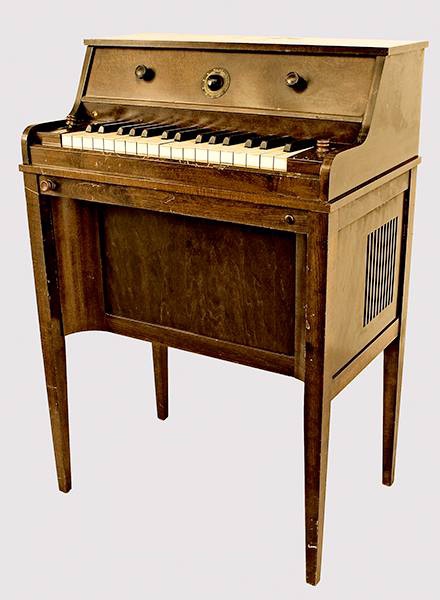
The Emicon at the
The Emicon at the National Music Museum (Vermillion, South Dakota, USA)

The Emicon (Model S) – the name derived from that of the distributors, M.I. Conn in New York – was designed in Budapest, Hungary by electronics engineer Nicholas Langer and Hungarian instrument designer, John Halmágyi and later manufactured in the USA. The Emicon was a monophonic 32 note keyboard controlled instrument based on the same type of heterodyning vacuum tube oscillator technology first used in the  Thereminvox a decade earlier. Langer designed the instrument to be able to create more complex tones than the standard vacuum tube sine wave and therefore used a single neon gas-discharge tubes to produce a type of sawtooth wave with richer harmonics; “In general, pure sinusoidal  oscillations, when converted into sound, are not satisfactory from the musical  point of view as they impress us as empty and meaningless” – Langer’s Emicon was said to be able to produce tones similar to a cello, saxophone, oboe, trumpet, mandolin, guitar and bagpipe and was said to be the instrument that inspired Harald Bode to start designing electronic musical instruments. Designed as a portable domestic instrument, The Emicon was housed in a shallow rectangular case small enough to sit on a tabletop and could be attached directly to a domestic radio receiver, public address system, amplifier, or any similar equipment. 1 Davies, Hugh,(2014) The Emicon, Electronic valve Instruments, Grove Online, 08 December 2014.

“Charles D. Stein shows a model how to play the Emicon at the Texas Centennial Exposition in Dallas in June 1936.”
Langer's patent for the Emicon
Langer’s patent for the Emicon

The Emicon was manufactured and marketed by Emicon, Inc., Deep River, Connecticut, CA from 1932. A later portable travelling model was built into case with an amplifier in separate case similar to later instruments such as the Ondioline. A single example of the Emicon survives at the Charles D. Stein Collection of Early Electronic Instruments at the National Music Museum, Vermilion, South Dakota, USA. Langer moved from Hungary to the USA sometime in 1932 and continued to develop improved versions of the Emicon and filed numerous patents for electronic musical instruments until the 1950s.

Images of an Emicon sold at an auction April 2023:


References

  • 1
    Davies, Hugh,(2014) The Emicon, Electronic valve Instruments, Grove Online, 08 December 2014. ↩︎

The ‘Rangertone Organ’. Richard H.Ranger, USA, 1932

Richard Ranger at the Rangertone Organ

The Rangertone Organ was a large electronic tone-wheel based organ developed by the electronics engineer and pioneer of audio recording Richard Ranger in the 1930’s. The instrument was marketed by Ranger from his own company ‘Rangertone Incorporated’ on Verona Ave. in Newark, NJ. Very few of the instruments were sold, one of which was installed at the Recital hall of Skinner Hall of Music, Vassar College. After the failure to sell the instrument Ranger went on to develop a series of high fidelity phonograph devices that never went into production. During WW2 Ranger spent time investigating German electronic equipment for the US Army and it was here that he picked up and removed for his own use the German AEG Magnetophone tape recorder. Ranger returned to the U.S. and in 1947 announced his new Rangertone Tape recorder, based on the Magnetophone, which finally gave the Rangertone Inc the financial success it needed until squeezed out of the domestic market by larger companies such as Ampex.

Richard Ranger with the wireless facsimile system
Richard Ranger with the wireless facsimile system. in 1924, Richard Ranger invented the wireless photoradiogram, or transoceanic radio facsimile, the forerunner of today’s fax machines. A photograph of President Calvin Coolidge sent from New York to London in November 1924 became the first photo picture reproduced by transoceanic radio facsimile.
The Rangertone Organ was one of the early tone wheel organs, similar to the Hammond Organ and much earlier Telharmonium (1906). Uniquely, the Rangertone Organ had its pitch stability controlled by tuning forks, therefore it was possible to change the temperament by changing the tuning of the forks. Timbre was controlled by push-buttons to the right of the keyboard, and/or by switching between six different amplifier/speaker combinations, which had different tremolo and tonal qualities.The original version was a huge machine, with more than 150 valves. A portable single-keyboard model was built for concert performance.1
Ranger made the first public demonstration of his huge  ‘pipeless organ’ at Newark, New Jersey in 1931:
Press telegram announcing Ranger's new instrument
Press telegram announcing Ranger’s new instrument in 1931. Image: Museum of Magnetic Sound Recordings, Austin Texas, USA. © 2018 Museum of Magnetic Sound Recording https://museumofmagneticsoundrecording.org/ManufacturersRangertone.html
Interior of the Rangertone organ. Image: Proceedings of the institute of Radio Engineers November 1936 Volume 24, Number 11, 1444.

“Ranger’s apparatus consisted essentially of twelve separate sets of motor-driven alternators precisely maintained at given rotational speeds, by tuning-fork control apparatus. One of these sets of alternators, as shown in Fig. 5, generated all the required C’s; another all the C sharps; another the D’s, and so forth. From these alternators he obtained all the desired fundamentals and their true harmonic frequencies for the tempered scale. Timbre control switches selected the partials and their amplitudes for any desired tone quality. Amplifiers were, of course, used with reproducers to translate the feeble audio currents into sound.

Ranger’s improvements over the basic work of Cahill were made possible by the advent of the vacuum tube. For example, he provides means for automatic selection of different amplifiers, for different simultaneously produced tones, to prevent cross modulation in a single amplifier; means for avoiding keying transients, for accentuating high or low frequencies, for restricting tremolo to specific components of a complex tone, and at different tremolo rates, means to provide glissando effects, for regulating the temperament, for providing damped wave trains in simulation of percussive tones, and numerous other details.” 1 Meissner, Benjamin. F,(1936) Electronic music and instruments, Proceedings of the institute of Radio Engineers November 1936 Volume 24, Number 11, 1444.

Ranger, Richard Howard – Inventor, USA *13.06.1889-10.01.1962+ with the Rangertone Organ 1930 – Image:  Sennecke Vintage property of ullstein bild (Photo by Robert Sennecke/ullstein bild via Getty Images)

References:

  • 1
  • 1
    Ranger made the first public demonstration of his huge  ‘pipeless organ’ at Newark, New Jersey in 1931:
    Press telegram announcing Ranger's new instrument
    Press telegram announcing Ranger’s new instrument in 1931. Image: Museum of Magnetic Sound Recordings, Austin Texas, USA. © 2018 Museum of Magnetic Sound Recording https://museumofmagneticsoundrecording.org/ManufacturersRangertone.html
    Interior of the Rangertone organ. Image: Proceedings of the institute of Radio Engineers November 1936 Volume 24, Number 11, 1444.

    “Ranger’s apparatus consisted essentially of twelve separate sets of motor-driven alternators precisely maintained at given rotational speeds, by tuning-fork control apparatus. One of these sets of alternators, as shown in Fig. 5, generated all the required C’s; another all the C sharps; another the D’s, and so forth. From these alternators he obtained all the desired fundamentals and their true harmonic frequencies for the tempered scale. Timbre control switches selected the partials and their amplitudes for any desired tone quality. Amplifiers were, of course, used with reproducers to translate the feeble audio currents into sound.

    Ranger’s improvements over the basic work of Cahill were made possible by the advent of the vacuum tube. For example, he provides means for automatic selection of different amplifiers, for different simultaneously produced tones, to prevent cross modulation in a single amplifier; means for avoiding keying transients, for accentuating high or low frequencies, for restricting tremolo to specific components of a complex tone, and at different tremolo rates, means to provide glissando effects, for regulating the temperament, for providing damped wave trains in simulation of percussive tones, and numerous other details.” 1 Meissner, Benjamin. F,(1936) Electronic music and instruments, Proceedings of the institute of Radio Engineers November 1936 Volume 24, Number 11, 1444. ↩︎

The ‘Electrochord’ and the ‘Kraft Durche Freude Grosstonorgel’. Oskar Vierling & Winston E. Kock, Germany, 1933

Oskar Vierling  born: 24. January 1904 in Straubing, Germany -  Died 1986
Oskar Vierling born: 24. January 1904 in Straubing, Germany – Died 1986

Oskar Vierling was an important figure in the development of electronic musical instruments and electro-acoustic instruments during the 1930’s to the 1950’s. Vierling was a trained electronic engineer who, after studying at the Ohm Polytechnic, Nuremberg filed over 200 patents. In 1935 Vierling moved to Berlin where he received his doctorate in physics at the Technical University and then continued to work at the  Heinrich-Hertz-Institute of Vibration Research (HHI) under Fritz Sennheiser.

The Electrochord

Electrochord at the Deutsches Museum in Munich

Vierling’s first musical instrument was the ‘Electochord’ an electro-acoustic piano designed and built in collaboration with  Benjamin Franklin Mießner and was commercially marketed by August Förster Piano Factory in Lõbau. The Elechtrochord worked by converting resonating piano strings via electro-magnets into electronic sounds in a similar way to Vierling’s Neo-Bechstien Piano (an early electro-acoustic piano designed by Vierling and Walther Nernst in 1931).

Vierling
Oskar Vierling working on the first version of the ‘Electrochord’

The vibrations from a normal piano string were recorded and amplified electronically. Various register circuits enabled the player to change the sound’s timbre ranging from “a delicate Spinettte, the lyrical tone of a parlour organ to the powerful sound emission of a grand piano”. A restored model of the Electrochord is kept in the music collection of the Deutsches Museum in Munich. During the early 1930’s Vierling worked closely with Jorg Mager at his Darmstadt research centre on the construction of Klaviatursphäraphon amongst other instruments.

Jorg Mager and Oskar Vierling working on the Sphäraphon at Mager's laboratory in Darmstad.
Jorg Mager and Oskar Vierling working on the Sphäraphon at Mager’s laboratory in Darmstadt.
The Neo-Bechstien Electro-acoustic piano

The ‘Kraft Durche Freude Grosstonorgel’

Keyboard fo the Grosstonorgel
Keyboard of the Kock-Vierlin KDF Grosstonorgel

Vierling went on to develop another large electronic organ; the ‘Grosstonorgel’ (together with  Karl Willy Wagner and the American engineer Winston E. Kock both at the Heinrich-Hertz-Institute. Winston Kock came to Berlin in 1933 as an exchange student at the Technical University of Berlin where he built an electronic organ for his diploma thesis. Since vacuum tubes were very expensive, he designed an instrument that relied instead on the smaller and cheaper neon tubes for the oscillators . He filed a patent for a use of inductive neon oscillators and sound-colour generation. It’s likely that the Grosstonorgel used similar neon or vacuum tube technology.

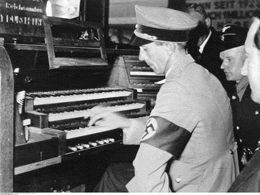
Joseph Goebbels at the GrosstonOrgel
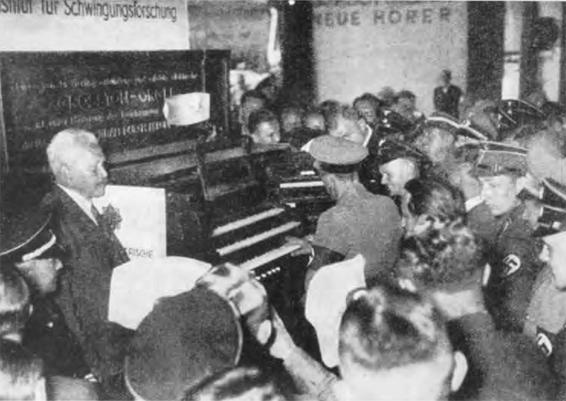
Joseph Goebbels at the GrosstonOrgel. HHI Berlin 1935
The workshop at the HHI. The GroostonOrgel being built.
The workshop at the HHI. The GrosstonOrgel being built.
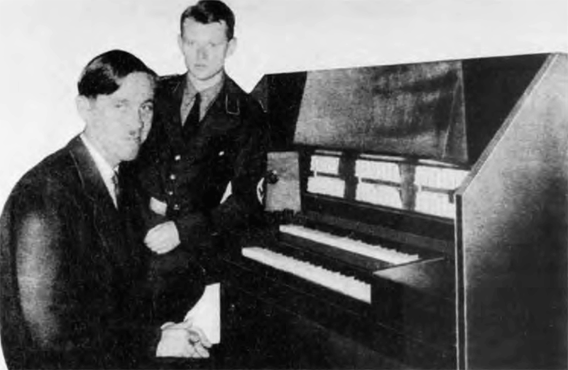
Winston Kock (seated) and Oskar Vierling at the keyboard of their Grosstonorgel.

Work on the Grosstonorgel was funded by the National Socialist ‘Kraft Durche Freude’ cultural association (‘Strength Through Joy’  Set up as a tool to promote the advantages of National Socialism to the people,which became the world’s largest tourism operator of the 1930s) . The Grosstonorgel, as well as a Vierling designed 500 watt PA system, was a one-off instrument specifically designed to provide the musical accompaniment to the 1936 Olympic Games. A year later the instrument was also used at the Reich Party Congress of the National Socialist Party in Nuremberg. The new improved model was said to be able to produce “beautiful bell sounds” to accompany the Nazi propaganda spectacle.

sennheiser_vierling_gto
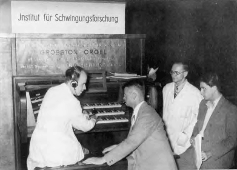
Fritz Sennheiser (seated) and Oskar Vierling with the kdf Grosstonorgel. HHI Berlin 1935.
The first broadcast of a concert consisting exclusively of electric instruments orchestra, organized by the "Radio Hour ', Berlin, 19 10 1932  The instruments were a Neo-Bechstein piano, Trautonium Heller ion, electric violin and cello, and two theremin instruments. Behind each instrument the corresponding speaker
The first electronic group? an purely electronic orchestra  organised by  “Radio Hour ‘ broadcast, Berlin, 19.10.1932. The instruments were a Neo-Bechstein piano, Trautonium, Hellertion, electric violin, electric cello, and two Theremins with a corresponding loudspeaker behind each instrument.
Jospeh Goebels tries the Grosstonorgel. HHI Berlin 1935.

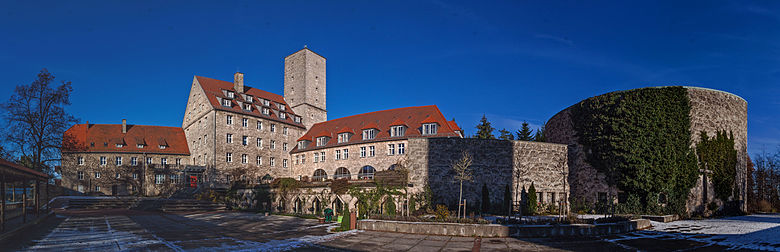
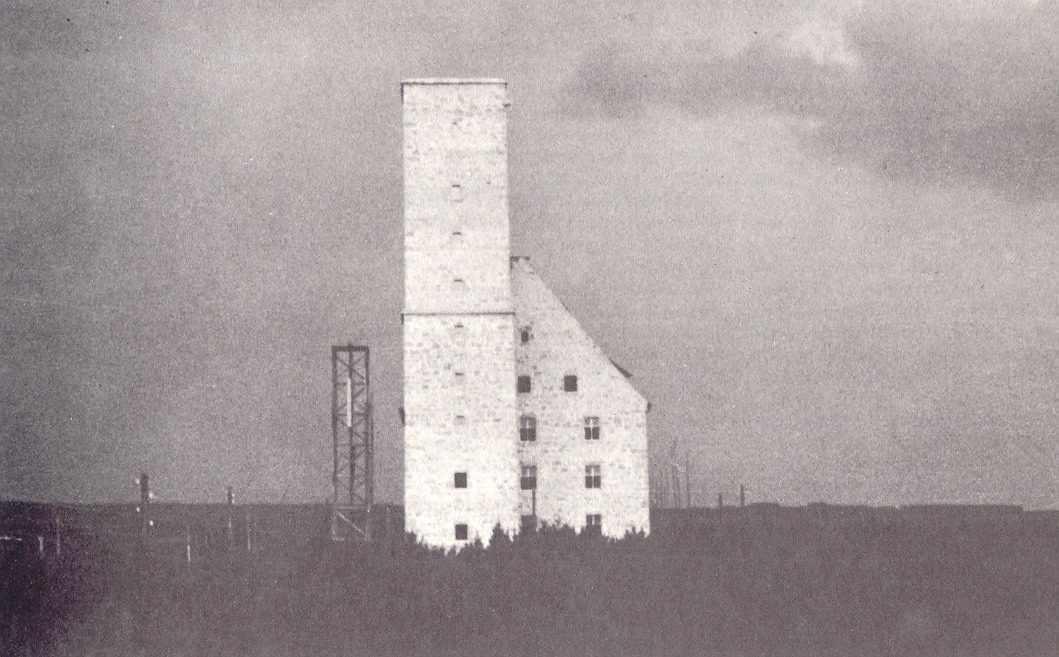
Vierling had joined the National Socialist Party (NDSAP)  in the late 1930s and in 1941 established the Vierling research group  with a staff of 200 employees co-operating directly with the Wermacht high command. The secret research establishment was located in Burg Feuerstein, Ebermannstadt disguised as a hospital with red-cross emblems on the roof to avoid allied bombing.

Burg Feuerstein home of the secret Vierling Research Group

Research included audio-controlled torpedoes (codenamed “wren” and “vulture” where the torpedoes located their target from the propeller noises of enemy ships ), encryption technology (with Erich Hüttenhain and Erich Fellgiebel on a voice encryption method of the legendary SZ 42 cipher ), anti radar submarine coating (codenamed “chimney sweep”) as well as radio control equipment and electronic calculators. The Vierling company still exists as a family run business in Ebermannstadt.

The remains of the Vierling after Allied bombing in 145
The remains of the Vierling research laboratories in Burg Feuerstein after Allied bombing in 1945

After the fall of Nazi Germany the Burg Feuerstein castle was sealed-off by the British troops. Vierling revealed his previously secret work which he had hidden in secret walled off chambers in the castle and collaborated openly with the new occupiers:

“Another major opportunity arose in the capture of the Feuerstein Laboratory on a small mountain near Ebermannstadt, which conducted research and preliminary development of experimental communications equipment. Its director Dr. Oskar Vierling, was picked up and interrogated.  He proved cooperative, reassembled most of his staff and put them back to work, allowing TICOM to exploit the target.”

Report from TICOM Team 1.

At this time Vierling met the British mathematician and the ‘Father of Computing’  Alan Turing (then working for TICOM ; Target Intelligence Committee), to discuss details of encryption and specifically the Enigma machine and Vierlings work on encrypted radio transmissions. Vierling then worked at Gehlen Organisation (an American run espionage organisation employing hundred of ex-Nazis ) on the design of bugging devices for the American occupation (echoing the career trajectory of Lev Termen) and from 1949 to 1955, having escaped the De-Nazification process through his collaboration with the occupying powers, became professor of physics at the Philosophical-Theological College in Bamberg, Germany. Vierling continued working at Vierling AG in Ebermannstadt and died in 1986.

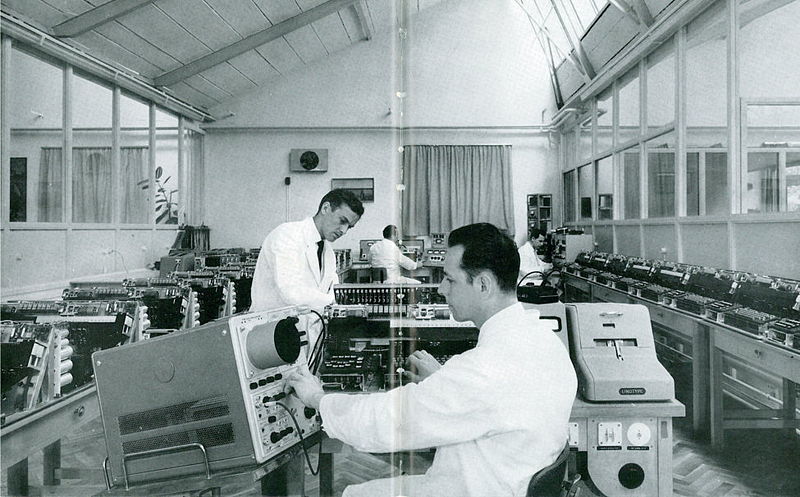
Vierling research laboratories in 1060
Vierling research laboratories in 1960


Kock and Vierling in Berlin

Excerpt from Hans-Joachim Braun’s ‘Music Engineers. The Remarkable Career of Winston E. Kock, Electronic Organ Designer and NASA Chief of Electronics’

“In the spring of 1933, after finishing his studies in Cincinnati, Kock became exchange fellow at the Technical University of Berlin. He had heard of Karl Willy Wagner’s work and wanted to conduct doctoral research with him at the Heinrich Hertz Institute. Kock’s counterpart as an exchange student from Berlin to Cincinnati was Sigismund von Braun, Wernher von Braun’s eldest brother. In Berlin Kock wrote a Ph. D. thesis on oscillations in inductive glow discharge circuits and, with Oskar Vierling, another student of Wagner’s, designed an improved electronic organ on the formant principle. Oskar Vierling, Kock’s collaborator on the Kock-Vierling organ, had studied electrical engineering at an engineering school and in 1925 joined the Laboratory of the German Research Institute for Telegraphy headed by Karl Willy Wagner. In 1928 he followed Wagner as his assistant to the newly founded ‘Institute for Vibration Research’ conducting acoustic research and designing electrified pianos and electronic organs. Together with the Nobel Laureate Walter Nernst he in 1931 designed the Neo-Bechstein piano, an electrostatic piano and from 1928 to 1935 developed his Electrochord for the piano manufacturer Förster. The National Socialist Strength through Joy organization sponsored Vierling’s ‘Strength through Joy Organ’ which was played at the Olympic Games in Berlin in 1936. This enlarged and improved version of the Kock-Vierling model created a sensation as did his electrically generated bell sounds which he presented at the National Socialist Party Rally in Nuremberg a year later.8 Fascination by technology, electricity and electronics,surprising effects, glorious sounds, this was food for the masses and much appreciated by the party propagandists. Vierling’s mentor Karl Willy Wagner must have watched his former assistant’s success with very mixed feelings, having himself been forced to resign from his directorate of the Heinrich Hertz Institute in 1936. There is an irony in the fact that Kock,who played a significant role in the US War effort during World War II, contributed, although unintentionally, to enhancing Nazi propaganda efforts.”


Sources

Peter Donhauser ‘THE FIRST ELECTRO-ACOUSTICAL PIANO IN GERMANY. THE NEO-BECHSTEIN AND IT’S RESTORATION’ Vienna Museum of Technology
Mariahilfer Strasse 212, 1140 Vienna

Hans-Joachim Braun ‘Music Engineers. The Remarkable Career of Winston E. Kock, Electronic Organ Designer and NASA Chief of Electronics’

‘Tarnname Schornsteinfeger’ by Thadeusz, Frank ‘Was wurde im Geheimlabor der Nazis auf Burg Feuerstein erforscht? Der Erfinder Oskar Vierling soll dort akustische Leitsysteme für die Wehrmacht entwickelt haben.’ Der Spiegel 18.04.2011

Wolfgang Voigt: Oskar Vierling, ein Wegbereiter der Elektroakustik für den Musikinstrumentenbau, in: Das Musikinstrument vol. 37, Nr 1/2, 1988, 214-221 und Nr. 2/3, 172-176.

http://www.vierling.de/

http://www.august-foerster.de

Final Report of TICOM Team 1. National Archives and Record Administration, College Park (NARA). RG 457, Entry 9037 (Records of the NSA), Box 168.

the ‘Syntronic Organ’ ,’Universal Recorder’ & ‘Photona’, Ivan Eremeeff, USA, 1932-1935.

Ivan Eremeeff holding a 9 inch sheet of sixty optical tones from the Syntronic Organ. Image: Popular Mechanics, January 1936,20-2.

The Syntronic Organ

In the early 1930s the world-renowned conductor and at the time the director of the Philadelphia Symphony Orchestra, Leopold Stokowski began to search for ways of augmenting or even replacing a conventional orchestra with amplified and electronic instruments. Stokowski, who had premiered many of Edgard Varese’s works in the 1920s and championed Varese’s experiments with electronic sound, added a Theremin Cello to the Philadelphia Orchestra to reinforce the double bass parts of the score – later replacing this with a specially adapted Ondes Martenot. 1 Davies, Hugh, (2014) Electronic Musical Instruments, The Grove dictionary of musical instruments, New York : Oxford University Press,168.
Eremeeff’s diagram of a networked orchestra of 20 Syntronic Organs. Image: US Patent 1,924,713,  June 4, 1932.
Ivan Eremeeff began a collaboration with Stokowski around 1932 with the aim of creating an all-electronic orchestra equipped with thirty five connected electronic instruments designed by Eremeeff:
“plans are being discussed with a view to a symphony orchestra which is composed exclusively of electronic organs, of which there will be about 35. The instruments are designed to be portable and compact, and will utilize the synthetic wave films as described, for the production of various types of music, such as produced by ordinary well-known musical instruments as the violin, the flute, the piccolo, etc. , and also music the timbre or tone of which has not been heard before.”
An artists depiction of Stokowski’s synchronised orchestra with multiple connected Syntronic Organs. Image: Popular Mechanics, January 1936, 20-2.
“The symphony orchestra of the future will not be a band of a hundred or more musicians, carrying a carload of instruments, but a small group of fifteen or twenty men, each carrying a small roll of film. This small group will be able to play symphonies and other selections with greater precision, and better effects, than could be obtained from an orchestra made up of hundreds of artists playing the finest musical instruments. In fact, they will be able to obtain effects that cannot even be approximated with actual musical instruments, since every instrument has its physical limitations.
The impulses from these various devices go to a ‘mixing board,’ where they are “mixed” and enter the loud-speakers. man at the mixing board controls the volume of the various instruments. With this arrangement, the conductor will not stand before the orchestra, but a motion picture will be taken of the orchestra leader con-ducting. The picture will be shown on a screen, and the operators of the devices will follow his leading on the screen.
The conductor himself will sit at the control panels situated in the audience. He will be able to regulate the speed at which the film run, and also regulate the sound. The conductor thus, at his ease, will get the same effect as the audience. The music itself will come from loud-speakers situated about the auditorium instead of emanating from the stage on which the musicians appear.”2 Music of the Future now a Reality, Popular Mechanics, January 1936, 20-2. 
Syntronic Organ circa 1933

The Syntronic project was based at the new WCAU building in Philadelphia and sponsored by the radio station’s president Dr Leon levy. The first product of this collaboration was the Syntronic Organ unveiled at WCAU in 1934. 3 Kassell, Edward, E, (1934) A “Syntronic” Organ, Radio Craft, August 1934, 77,104-6. The Syntronic Organ was designed specifically for a networked orchestra of interconnected electronic instruments – i.e. ‘Synchronised – Electronic’ or, as Eremeeff described it in his 1932 patent:

“a system consisting of one or more synchronously coupled electrical musical instruments, each of which is capable of producing electrically tones of predetermined pitch, predetermined synthetic quality, and predetermined tonal expressions, the latter being produced by various keying means, with provision, if desired, for tremolo and a continuing diminishing of the tones after the keying has been discontinued.”4Eremeeff, Ivan, (1932), SYNTHETIC ELECTRICAL MUSICAL SYSTEM. US Patent 1,924,713, filed June 4, 1932 .
The dual keyboards of the Syntronic Organ. Image: Popular Mechanics, January 1936, 20-2.

The Syntronic Organ was a photo-electric type instrument controlled by two manual keyboards each controlling its own sound producing unit and it was designed, not just to reproduce the sound of a pipe organ, but be able to electronically recreate all the instruments of the orchestra and numerous new sound effects. Thomas Rhea described in detail the technical operation of the instrument in The Art of Electronic Music:

“This instrument is yet another of the type that has a stationary illuminated mask governing tone colour. However, Eremeeff departed from the typical tone-wheel design. Instead he used a film with transparent “light slits” which passed rapidly over the photoelectric cell. Some models had a “pitch film” that would run for a limited time — just like a tape recorder. Another version had an endless-loop pitch film. The following is a synopsis of the operating principles of the Syntronic Organ (please refer to the diagram fig1.):

The rapidly moving pitch film (a) rode on padded rollers, driven by a variable-speed motor that allowed tuning. The quality mask (b ) was divided into sections and could be advanced manually (c ) or by motor (d) to provide a selection of tone colours. Light from sources (e ) was projected through the selected quality mask, then through variable “translucency disks” (f,g) which provided pedal control of volume and speed of tremolo. Finally the light passed through the running pitch film (a) onto a photo- electric cell. When a given key was depressed, an associated light shutter (h) was raised. This allowed the light to pass through the quality mask and fall on a single pitch track of the film. (The instrument was completely polyphonic, having 88 such shutters. ) The light shutters rode in the spacers of the “diminishing rollers” (i). which revolved at a controllable speed in the direction which would cause the light shutters to return to their original position (creating silence ). The Syntronic Organ’s envelope (loudness ) control was remarkable. Each light shutter had a spring that held it against the diminishing rollers. A pedal could be used to simultaneously alter the speed of these rollers, and control the volume using the translucency disk (i) permitting the tones to fade away. That is, the Syntronic Organ could hold the sound and create a gradual release after the fingers left the keyboard — like a synthesizer. When spring tension was released, the shutters were freed: then when a key was depressed, its associated shutter would drop by its own weight back to its resting place. This created short tones comparable to staccato tones on a piano —or “zero sustain” on a synthesizer envelope generator that controls the voltage-controlled amplifier. Also. the 88-note keyboard was scaled so that “… each frequency of the musical scale has its own predetermined intensity.” Eremeeff designed not only this fascinating instrument, but the entire technology necessary for its support. He constructed a “universal” recorder capable of creating pitch and quality films by exposing running film to light patterns generated by a “flicker box.” The pitch films were composed of numerous repeating uniform slits or apertures produced by rotating cams of the appropriate shape; light was permitted to pass through their openings and expose the film, creating tracks of definite frequency. To prepare quality films (masks ), the recorder used cams with predetermined wave patterns cut into their peripheries, these too, revolved in the path of the light beams projected onto the running raw film. Naturally, the quality tracks were produced in a size that would correctly correspond to the associated pitch track.5 Rhea, Thomas, L,(1984) Photo-Electric Instruments, The Art of Electronic Music – GPI Publications, 13.

Stokowski’s ambitious plans for an all electronic orchestra ultimately never came to fruition because of disagreements between Stokowski and the orchestra’s management. Stokowski re-visited the plan with a mixed 150 acoustic and 24 electronic instrument orchestra for San Francisco 1939 Golden gate Exhibition – a plan that similarly failed to materialise. it seems that Stokowski’s disagreements with the Philadelphia Symphony orchestra’s management board and his frustration at being unable to realise his musical-technical vision lead to his eventual retirement from the orchestra in 1941.6 Davies, Hugh, (2014) Electronic Musical Instruments, The Grove dictionary of musical instruments, New York : Oxford University Press,168.

The WCAU Photona

The Photona at WCAU Philadelphia played by Leonard ‘Melody-Mac’ MacClain in 1935. Image: Theatre organ, 1962.

Ivan Eremeef later created the Photona , a cut-down commercial version of the Syntronic Organ. This instrument followed the same photo-electrical system as the Syntronic Organ and was developed by Eremeeff with the  John Leitch at the engineering department of  WCAU broadcasting station in Philadelphia, USA. The Photonahad twelve rotating optical discs illuminated by nine hundred six volt lamps. The instrument was played with two six octave manual keyboards and two foot pedals for volume and tremolo. The instrument its official debut on February 10, 1935, according to nation-wide press reports, and was officially presented to the public over coast-to-coast radio broadcasts and abroad, for 6 months, beginning on April 6, 1935. An article in the Theatre Organ describes the launch of the Photona:

“Leonard MacClain played the first electronic organ over a coast to coast broadcast on April 6, 193 5. It was the newly invented Photona, built by Ivan Eremeeff, on the photo-electric cell principle. Asked what he thought of it, Mac re plied, “It be longs in an institute!” And that is where it is today – the Franklin Institute. It has no pedals, and was very noisy, with the speaker placed in another room to get away from the racket. Cost of the device was $76,000.” 7 Klos, Lloyd, E (1962) “Melody Mac” the Giant of the T.O. World, the Theatre Organ, 6.

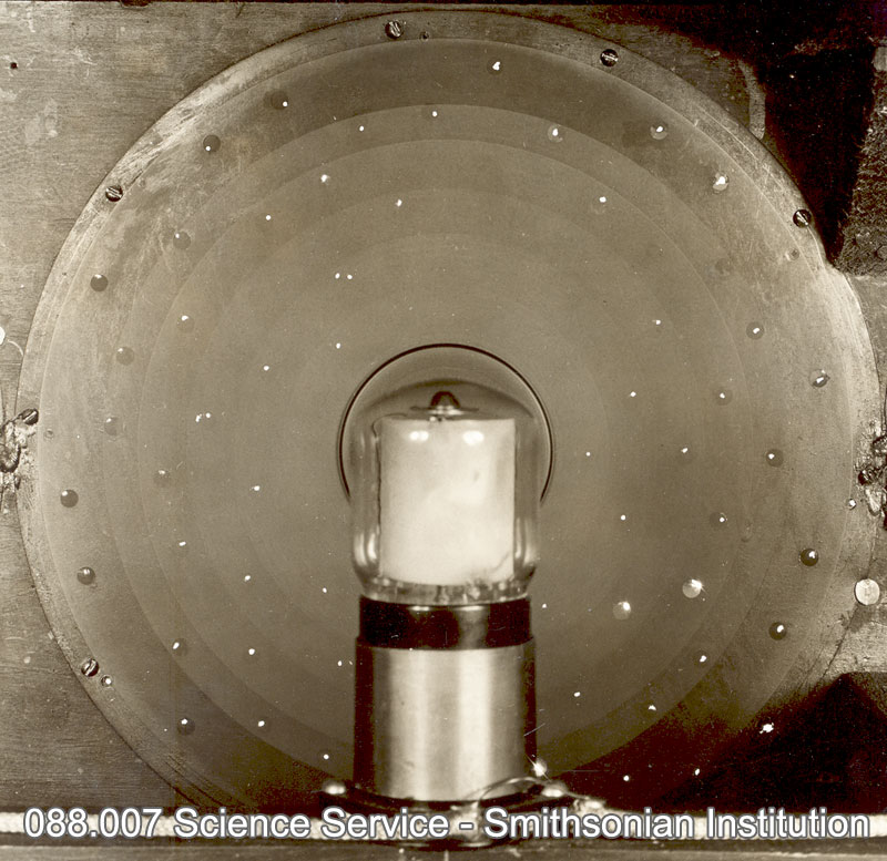
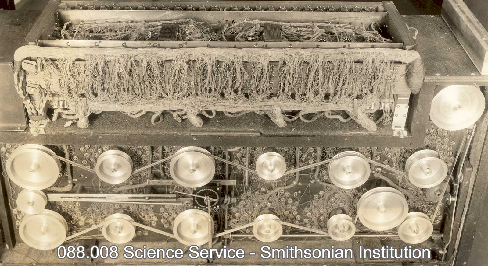
The Photona used a very simple system of twelve rotating light choppers, that worked to interrupt light periodically. Evidently no tone masks were used and the output was probably a complex wave. The twelve disks were cut radially with slots at several depths toward the centre of the disk, allowing for the production of harmonic or inharmonic overtones. The instrument is reported to have used 900 car lamps, switched on by keys, for the production of sound.8 “WCAU’s ’Photona’ Organ,” Electronics, April, 1905, p. 123. Thomas Rhea, again describes the function of the Photona:

“The lamps were connected, through different circuits, to the keyboard of two 73-note manuals and to “stops” which governed tone control. When a key on a manual was depressed, corresponding lamps were lit and the appropriate tone was “chopped” by the tone wheel. For timbre control, the partials of any tone could be varied in strength with knobs which increased or decreased the amount of current feeding into the appropriate lamps. Alternating current was used for keying these lamps; the Photona was constructed using no rectifiers (AC to DC converters ). Eremeeff was a designer with an car for musical nuance. In addition to the volume-control pedal that was standard fare for instruments of the era, he arranged for foot-operated control of vibrato amount. This was accomplished with a mechanical linkage that engaged a cam with a motor-driven gear; this in turn caused the displacement of the tone-generator drive belt on a cone- shaped pulley, creating true vibrato, as opposed to the constant-amount vibrato on some electronic musical instruments today. The Photona also had a “percussion push” button that caused a sudden rush of current to the photoelectric cells, creating a cracking, percussive sound. Maybe Eremeeff was trying to provide a rudimentary dynamic keyboard for touch-responsive phrasing. Even though the Photona had an impossibly complex tone generator, there were sparks of genius in its musical engineering.9 Rhea, Thomas, L,(1984) Photo-Electric Instruments, The Art of Electronic Music – GPI Publications, 13.

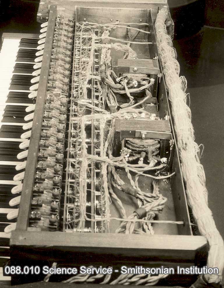
Photo-cell behind a revolving disc.
Photo-cell behind a revolving disc. Image: Smithsonian Institution Science Services.
The WCAU Photona at the Smithsonian Institution
The WCAU Photona at the Smithsonian Institution: Image: Smithsonian Institution Science Services.
The driving pulleys for the tone discs and transformers used for lighting and nine hundred six volt lamps
The driving pulleys for the tone discs and transformers used for lighting and nine hundred six volt lamps. Image: Smithsonian Institution Science Services.

Ivan Eremeeff’s patents for a photo-electrical instrument 1934-6

Biography: Ivan Ivanovich Eremeef (1893 – ?)

Ivan Eremeeff (later Americanised to Ivan Jerome) was a Russian-American physicist, prolific inventor and designer of electronic instruments. Born in Chelyabinsk, Russia in 1893 , he probably emigrated to the USA about 1918, and began experimenting with the construction of electronic instruments about 1923 in Dayton, Ohio, where he also developed a four rotor H-1 helicopter for the US army (1922) a barograph (1928) and a mobile aircraft hangar (1922).

Eremeeff and Bothezat’s design for a four rotor military helicopter the ‘Flying Octopus’: December 18, 1922, The first helicopter actually to fly, designated the Engineering Division H-1, was designed by Dr. George de Bothezat and Mr. Ivan (Eremeeff) Jerome.

In 1930 he moved to Philadelphia, where he founded and chaired the Society of Electronic music and took out eight patents for electronic instruments between 1932 and 1936 including the including the Gnome (1933 patent), a larger variant of the Gnome (1933), the Syntronic Organ (1934) and the Photona (1935). In the early 1930s he worked at the electronic music laboratory of the radio station WCAU in Philadelphia.

Eremeeff’s electronic instruments were based on two different sound-generating systems: electromagnetic tone-wheels, a principle he used in the Gnome, and photoelectric devices – Photona (or WCAU organ; 1935) and Syntronic organ (1934). The last instrument was enthusiastically endorsed by Leopold Stokowski, and inspired him to plan with Eremeeff an electronic orchestra, but this project was never realized. In spite of their names, Eremeeff did not attempt to recreate the tone qualities of a pipe organ in either of his two photoelectric instruments. An unusual feature of all his electronic instruments was the addition of a vibrato pedal to the normal volume pedal, and in two of them there was also a control for the decay of the notes. Eremeeff claims to have experimented with  prototypes of a Theremin like instrument intended to produce not only tones but light and odours. In the 1953 he filed a suit against Hammond Organ Co. for patent infringement of his ‘photoelectrical musical system’ which was ultimately dismissed for lack of prosecution in January 1957. 10Davies, Hugh (2014) Electronic Instruments, The Grove dictionary of musical instruments, New York : Oxford University Press, 167. 11Patent Suits. Notices under 35 U.S.C . 290 Patents act of 1952, 529.

In 1938 Eremeeff returned to aviation and created a design for a supersonic aircraft.12 Plane with the Speed of Sound Is Proposed by Designer, Popular Mechanics Magazine 1938-12: Vol 70 Iss 6, 833. After World War II, Eremeef/Jerome set up a lucrative business designing optical instruments and precision aerial cameras for the US army and moved to Southampton New York. In 1955, aged 62, Eremeev/Jerome hit the headlines when he was charged with creating obscene and pornographic films and corrupting minors at his Southampton mansion. Eremeev/Jerome jumped a $100,000 bail bond and fled the country. 131956, OBSCENE AND PORNOGRAPHIC LITERATURE AND JUVENILE DELINQUENCY INTERIM REPORT OF THE SUBCOMMITTEE TO INVESTIGATE JUVENILE DELINQUENCY TO THE COMMITTEE ON THE JUDICIARY PURSUANT TO S. Res. 62, and S. Res. 173 (84th Congress),7


References:

  • 1
    Davies, Hugh, (2014) Electronic Musical Instruments, The Grove dictionary of musical instruments, New York : Oxford University Press,168. ↩︎
  • 2
    Music of the Future now a Reality, Popular Mechanics, January 1936, 20-2.  ↩︎
  • 3
    Kassell, Edward, E, (1934) A “Syntronic” Organ, Radio Craft, August 1934, 77,104-6. ↩︎
  • 4
    Eremeeff, Ivan, (1932), SYNTHETIC ELECTRICAL MUSICAL SYSTEM. US Patent 1,924,713, filed June 4, 1932 . ↩︎
  • 5
    Rhea, Thomas, L,(1984) Photo-Electric Instruments, The Art of Electronic Music – GPI Publications, 13. ↩︎
  • 6
    Davies, Hugh, (2014) Electronic Musical Instruments, The Grove dictionary of musical instruments, New York : Oxford University Press,168. ↩︎
  • 7
    Klos, Lloyd, E (1962) “Melody Mac” the Giant of the T.O. World, the Theatre Organ, 6. ↩︎
  • 8
    “WCAU’s ’Photona’ Organ,” Electronics, April, 1905, p. 123. ↩︎
  • 9
    Rhea, Thomas, L,(1984) Photo-Electric Instruments, The Art of Electronic Music – GPI Publications, 13. ↩︎
  • 10
    Davies, Hugh (2014) Electronic Instruments, The Grove dictionary of musical instruments, New York : Oxford University Press, 167. ↩︎
  • 11
    Patent Suits. Notices under 35 U.S.C . 290 Patents act of 1952, 529. ↩︎
  • 12
    Plane with the Speed of Sound Is Proposed by Designer, Popular Mechanics Magazine 1938-12: Vol 70 Iss 6, 833. ↩︎
  • 13
    1956, OBSCENE AND PORNOGRAPHIC LITERATURE AND JUVENILE DELINQUENCY INTERIM REPORT OF THE SUBCOMMITTEE TO INVESTIGATE JUVENILE DELINQUENCY TO THE COMMITTEE ON THE JUDICIARY PURSUANT TO S. Res. 62, and S. Res. 173 (84th Congress),7 ↩︎