‘Instrument de Musique Electronique’ – A diagram from Hugoniot’s patent for a tone-wheel sound generator, December 1919. Image: French Patent Office FR22866 – 05/09/1921.
Charles–Emile Hugoniot (died in France, 1927) was a French mechanic, researcher, and inventor of early electronic musical instruments. Hugoniot was awarded seven patents in France between 1919 and 1923 for various methods of sound generation, including tone wheels and photoelectric tone generators. Starting in 1919, Hugoniot began a process of improving existing sound generation devices of the period, first, Thaddeus Cahill’s electro-magnetic tone-wheels (from Cahill’s patents that would have been known to him in France) and continuing to electromagnetic steel discs and photo-electrical methods, possibly influenced by the South African physicist, Hendrik van der Bijl’s patents from 1916. By doing so, Hugoniot introduced these new methods to a French group of electronic engineers.
Hugoniot appears to have constructed only one instrument– a photoelectric organ described in his patent #FR550370 in 1921. The instrument was among the first to use a photoelectric technique to generate sound: Hugoniot projected a light beam onto a selenium photovoltaic cell through an array of 12 rotating discs, each cut with concentric rings of radial slits. The frequency (and speed of rotation) generated an electrical pulse from the photo-voltaic cell that equated to an octave pitch.
Hugoniot died in 1927 before he could develop his ideas beyond prototypes, yet he left a legacy of innovation that influenced a new generation of French pioneering instrument designers, including Pierre Toulon and Givelet & Coupleaux.1 Bush, D., & Kassel, R. (2004;2006;). The Organ: An Encyclopaedia, London: Taylor and Francis, 167.
Hugoniot’s patent for a photo-electrical sound generator, August 1921. Image French Patent Office FR550370D – 08/27/1921.
Benjamin Miessner, writing in the Proceedings of the Institute of Radio Engineers, USA 193,6 describes Hugoniot’s photo-electric sound generation ideas:
“With this scheme the various types of wave forms for different timbres may be placed in radial sectors on a disk; another disk carrying the scanning slits in circular tracks rotates before this wave-form disk. A source of light and photocell complete the translating arrangements. Each slit track scans its corresponding wave cycle at a speed corresponding to one pitch of an approximate tempered scale. Thus, one wave and one slit track serve for each tone frequency of the tempered scale. Naturally the lowest pitch tracks are nearest the center and the highest are nearest the circumference of the scanning disk.
Another interesting arrangement is that used by Lesti and Sammis in the Polytone. Here, instead of using a series of similar wave-form cycles on a continuous track, with a single scanning device, only one complete such cycle is used with periodic scanning by a series of similar scanning slits, equispaced on a continuous track. The slit spacing is precisely equal to the wave-form lengths, so that this wave form is repeated at the scanning frequency; i.e., the number of slits passing it per second. The same method was disclosed as early as 1921 by the French inventor Hugoniot, who described an electrical musical instrument of this type in his patent”.2 Miessner, Benjamin F, (1936) Electronic Music and Instruments, Proceedings of the Institute of Radio Engineers, New York, N.Y. Volume 24, November 1936, Number 11, 1427.
References
1
Bush, D., & Kassel, R. (2004;2006;). The Organ: An Encyclopaedia, London: Taylor and Francis, 167.
2
Miessner, Benjamin F, (1936) Electronic Music and Instruments, Proceedings of the Institute of Radio Engineers, New York, N.Y. Volume 24, November 1936, Number 11, 1427.
Created by the French engineer Pierre Marie Gabriel Toulon, with assistance from the electronic engineer Krugg Bass, the Cellulophone (“Cellule Photo-électrique”) made its debut as a prototype in France in 1927. The Cellulophone was an electro-optical tone generator instrument resembling an electronic organ controlled by two eight-octave keyboards and a foot pedal board. The instrument’s sound was created using a photo-electrical technique: a light beam was projected through slits in a variable-speed rotating disk cut with a number of equidistant slits – 54 slits for the lowest note, with different-shaped masks to create varied timbres. The light beam projected through the slits of the disk onto a photoelectric cell, which in turn generated an audible voltage pulse from a single vacuum-tube oscillator; the speed of the rotating disk, therefore, determined the frequency of the instrument’s output signal.
The Cellulophone used four tungsten-filament lamps to produce constant light beams, which were directed via mirrors and lenses through a single rotating disk onto a single selenium photocell, producing an amplified voltage signal from a vacuum tube. Toulon’s design, however, included a number of optical filters or ‘shutters’ that could modulate the tonal timbre of the instrument, allowing for complex overlapping timbral tones to be created. 1 Toulon, Pierre Marie Gabriel,(1934), Music Instrument Working Through a Keyboard and Photo-electric Cell, US Patent Office Granted Feb 1934, No.1948,996. Despite these innovations, according to Tom Rhea, the Cellulophone’s use of a single disk to create all twelve semitones in an octave meant that the instrument was constantly out of tune – i.e. above the 0.1% accuracy range. 2 Rhea, Tom, (1984) Photo-electric Instruments, The Art of Electronic Music, GPI Publications 1984, 13.
Pierre Toulon’s original 1928 patent of the Cellulophone ‘ Music Instrument Working Through a Keyboard and Photo-electric Cell’. Image: US Patent Office Granted Feb 1934 No.1948,996
Toulon’s Cellulophone won the Prix Jean Bares in 1933:
“Second prize (2,500 francs) was awarded to Mr.. Pierre Toulon, a father of three children and consulting engineer of the Electrical School, who made a large number of inventions, among which include “the relay arc” whose principle is applied in instruments referred to as “Thyratrons” and “Spark-gap convertors”, the latter enabling flattening and straightening of even high-powered electrical currents.
Mr Toulon also invented a device called “Cellulophone” – a musical instrument keyboard developed by the Pleyel company, which is an extremely reduced-size organ.” 3 Les Prix Jean S. Barès 1933, Office national des recherches scientifiques et industrielles et des inventions (France), 1934-10-01, 280.
The Cellulophone was one of a generation of instruments in the 1920-30’s that used a photoelectric sound-generation method; other examples include the Licht-ton Orgel, the Photona, the Superpiano,and the Radio Organ of a Trillion Tones. The increased sophistication and reliability of post-war electronic circuitry marked the decline of light-based synthesis after the 1940’s, except for a few pioneers such as Daphne Oram, who used a similar Oramics system to synthesise and sequence sounds.
Pierre Toulon, who held numerous related patents for early television scanners, electrical relays, large-screen televisions, audio amplifiers and sound reproduction and transmission devices, also proposed in the 1930’s a technique of speech synthesis using fragments of optical film mounted on a rotating drum.
A 1928 Extract from La Revue Hebdomadaire describes various new electronic instruments of the period, including the Cellulophone:
CHRONIQUE SCIENTIFIQUE. LA MUSIQUE RADIOPHONIQUE
Les concerts du professeur Theremin. Une expérience d’acoustique fort instructive. Battements électriques. Où interviennent les lampes à trois électrodes de la T. S. F. Le principe de l’éthérophone. Un précurseur. Piano et orgues radio électriques. Le cellulophone. Conclusion. On a beaucoup parlé ces derniers temps d’une rénovation de l’art musical par l’emploi d’instruments de musique utilisant la merveilleuse souplesse des ondes hertziennes. Les concerts donnés cet hiver à Paris par le professeur Léo Theremin, de Léningrad, ont attiré un nombreux public. Il n’est pas douteux que l’idée d’utiliser les ondes hertziennes à la production des sons puisse constituer une innovation heureuse. Essayons donc de décrire le merveilleux appareil du professeur Theremin et d’en faire comprendre le fonctionnement.
L’explication paraîtra très simple à tous les sans-filistes. Quant à mes autres lecteurs, s’ils veulent bien me prêter quelque attention, je suis certain qu’ils saisiront tout aussi aisément le principe de la musique radiophonique. Rappelons tout d’abord une expérience d’acoustique que chacun peut répéter, pourvu qu’il possède chez lui quelque instrument de musique.
Tout le monde sait que le son est produit par les vibrations de la matière et qu’il nous paraît d’autant plus aigu que les vibrations sont plus rapides. Lorsqu’on fixe l’extrémité d’une tige d’acier, une lame de fleuret par exemple, dans un étau, et qu’après l’avoir écartée de sa position on l’abandonne à elle-même, elle entre en vibration et produit un son, d’abord très grave, mais qui monte de plus en plus au fur et à mesure qu’on raccourcit la lame, ce qui augmente le nombre des oscillations par seconde. Les sons les plus graves que l’on puisse entendre correspondent à environ 30 vibrations par seconde, et les sons les plus aigus à 40 000. Entre ces limites s’étend toute la gamme des sons perceptibles.
Mettons en bran le deux diapasons identiques, donnant par exemple chacun le la normal, l’un d’eux ayant été désaccordé par un peu de cire fixée sur l’une des branches. Le diapason normal effectuant 435 vibrations par seconde, celui qui a été désaccordé en donnera par exemple 432. Dans ces conditions, lorsque les deux diapasons fonctionnent en même temps, on perçoit dans le son d’ensemble des renforcements et des affaiblissements sucessifs,des sortes de hou, hou, hou, répétés régulièrement etqu’on appelle des battements. L’expérience a permis de constater que le nombre deces hou, hou, hou. par seconde est exactement égal à la différence entre les nombres de vibrations par seconde que donnent séparément les deux diapasons, soit ici 435 diminué de 432. Il y a donc trois battements par seconde. Le phénomène est général. Chaque fois qu’on produit simultanément, au moyen d’appareils quelconques, deux séries de mouvements vibratoires dont les nombres d’oscillations par seconde sont différents, l’ensemble donne lieu à des renforcements et à des affaiblissements successifs,à des battements. Or les ondes hertziennes résultent d’une sorte de mouvement vibratoire d’un milieu hypothétique qu’on suppose répandu partout et auquel on a donné l’antique nom d’éther. Dans les ondes, dites entretenues, qu’utilise la radiophonie, les vibrations sont très régulières mais extrêmement rapides. Elles se produisent à raison de quelques centaines de mille par seconde. Envoyées directement dans un téléphone, ces ondes seraient sans actionsur lui, car à supposer qu’elles fussent capables de faire vibrer, suivant un rythme de quelques centaines de mille par seconde, la membrane du téléphone, nous serions incapables de percevoir des vibrations aussi rapides, pour les quelles notre oreille est atteinte d’une surdité absolue. Mais émettons simultanément, au moyen de deux appareils différents, deux séries d’ondes hertziennes, les unes, pour fixer les idées, à raison de ioo ooo vibrations par seconde, et les autres, à raison de 99 000. Leur production simultanée donnera naissance à des battements électriques, à des renforcements suivis d’affaiblissements des ondes hertziennes, dont le nombre par seconde sera égal à 100,000 diminué de 90,000. Et à ces battements électriques qui se produisent ainsi à raison de 1,000 par seconde, le téléphone peut être rendu sensible. Sa membrane oscillant à raison de r 000 vibrations par second eémettra un son aisément perceptible. Si donc, l’une des deux séries d’ondes demeurant invariable et se produisant toujours à la fréquence 100 000, nous avons le moyen de faire varier la fréquence de l’autre série d’ondes et de la rendre égale par exemple à 99,500, à 99,400, à 99,300. le nombre des battements, toujours égal à la différence des fréquences associées, sera successivement 500, 600, 700. par seconde. Le téléphone actionné par les battements fournira un son deplus en plus aigu, correspondant successivement à 500, 600, 700. vibrations par seconde. Et c’est là tout le secret de l’éthérophone. Des ondes hertziennes sont produites à la fréquence moyenne de 300 ooo vibrations par seconde par deux générateurs appelés hétérodynes. Si les deux séries d’ondes sont légèrement désaccordées, elles donnent lieu à des battements électriques qui, agissant dans un haut-parleur à la manière habituellement utilisée dans les réceptions radiophoniques, en actionnent la membrane et produisent un son. De la boîte où sont enfermées les deux hétérodynes émergent une tige métallique verticale jouant le rôled’antenne, et une spirale en fil de cuivre placée horizontal ement sur le côté. Le fonctionnement de l’appareil consiste à faire varier les constantes électriques de l’un edes deux séries d’ondes en approchant la main droitede l’antenne verticale et la main gauche de la spirale. Le premier mouvement fait varier la fréquence des battements et, par conséquent, détermine la hauteur de lanote le second mouvement agit sur l’amplitude des ondes et par suite sur l’intensité du son. De ces deux mouvements, le premier, qui doit suivre les notes de la partition musicale, est évidemment le plus compliqué etest de ce chef dévolu à la main droite le second est réservéà la main gauche en raison de sa simplicité.
L’idée qui est à la base de l’éthérophone n’est pas nouvelle. Dès 1917, les ingénieurs français travaillant au laboratoire de la tour Eiffel avaient songé à tirer un parti musical des battements radio-électriques dont nous venons de parler. M. Armand Givelet, vice-président du Radio-Club de France, avait eu l’idée de marquer à la craie sur le cadran du condensateur d’hétérodyne le réglage correspondant aux différentes notes de la gamme. En tournant rapidement ce condensateur variable et en arrêtant brusquement l’aiguille sur les repères du cadran, il était parvenu assez facilement à jouer des mélodies populaires simples. C’était, en somme, exactement le principe de l’éthérophone. Il a suffi de perfectionner quelques détails pour obtenir un appareil permettant de produire des effets véritablement artistiques.
D’ailleurs, M. A. Grivelet a réalisé, il y a quelques années, le premier piano radio électrique. On a pu voir cet instrument exposé récemment au premier Salon des Sciences et des Arts, au Grand Palais des Champs-Élysées. Chaque note est produite par un circuit séparé, engendrant les vibrations sans qu’il ait à intervenir des battements. De son côté, M. Bertrand a construit sous le nom d’orgue radio électrique un appareil d’un principe tout à fait analogue à celui du professeur Theremin, qui utilise les battements électriques de deux hétérogynes, et dans lequel le son est diffusé par un haut-parleur de grand modèle. La variation de la hauteur du son est produite par la commande d’une manette qui se déplace devant un cadran comportant une gamme de trois octaves.
Le Cellulophone de M. Pierre Toulon n’est pas moins curieux. Son principe est tout différent. Il utilise la propriété des cellules photoélectriques, sortes de piles qui donnent naissance à un courant lorsqu’elles reçoivent un faisceau de lumière. En envoyant sur une cellule, non un éclairage continu, mais un éclairage intermittent qu’on peut réaliser en interposant entre la source lumineuse et la cellule un disque tournant perforé, la pile produit une succession de courants instantanés dont le nombre par seconde dépend du nombre des trous que porte le disque et de sa vitesse de rotation. Envoyés dans un haut-parleur, ces courants le font vibrer avec la même fréquence. La hauteur de la note musicale dépend ainsi du nombre de trous que porte le disque et de sa vitesse de rotation, le timbre étant déterminé par la forme de ces trous. On conçoit qu’on puisse modifier à volonté la hauteur et le timbre, et obtenir des effets musicaux très variés.
Il serait difficile de prédire l’avenir qui est réservé aux appareils de musique radio électriques. Indiquons seulement qu’ils ont permis d’obtenir des effets artistiques très intéressants, et il ne serait pas surprenant que,grâce à eux, la musique, cette forme si élevée et si expressive de l’art qui a très peu évolué depuis des siècles, entre dans une voie entièrement nouvelle. A. BOUTARIC. 4 Boutaric, A. (1928), CHRONIQUE SCIENTIFIQUE. LA MUSIQUE RADIOPHONIQUE, La Revue Hebdomadaire: romans, histoire, voyages, Paris, mars 1928, 504 .
And from Le Genie Civil, February 7, 1928:
‘Le Cellulophone’ from Le Genie Civil, 18 February 7th, 1928.
References:
1
Toulon, Pierre Marie Gabriel,(1934), Music Instrument Working Through a Keyboard and Photo-electric Cell, US Patent Office Granted Feb 1934, No.1948,996.
2
Rhea, Tom, (1984) Photo-electric Instruments, The Art of Electronic Music, GPI Publications 1984, 13.
3
Les Prix Jean S. Barès 1933, Office national des recherches scientifiques et industrielles et des inventions (France), 1934-10-01, 280.
4
Boutaric, A. (1928), CHRONIQUE SCIENTIFIQUE. LA MUSIQUE RADIOPHONIQUE, La Revue Hebdomadaire: romans, histoire, voyages, Paris, mars 1928, 504 .
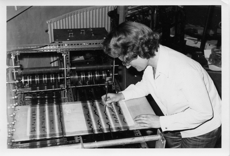
Daphne Oram working at the Oramics machine at Oramics Studios for Electronic Composition in Tower Folly, Fairseat, Wrotham, Kent
The technique of Oramics was developed by the composer and electronic engineer Daphne Oram in the UK during the early 1960s. It consisted of drawing onto a set of ten sprocketed synchronised strips of 35mm film which covered a series of photo-electric cells that in turn generated an electrical charge to control the frequency, timbre, amplitude and duration of a sound. This technique was similar to many previous photo-electric sound synthesis systems such as Yevgeny Sholpo’s Variophone some years earlier in Leningrad, the Superpiano (1928) and probably the earliest, the Luminaphone of 1925. The output from the instrument was only monophonic relying on multi-track tape recording to build up polyphonic textures.
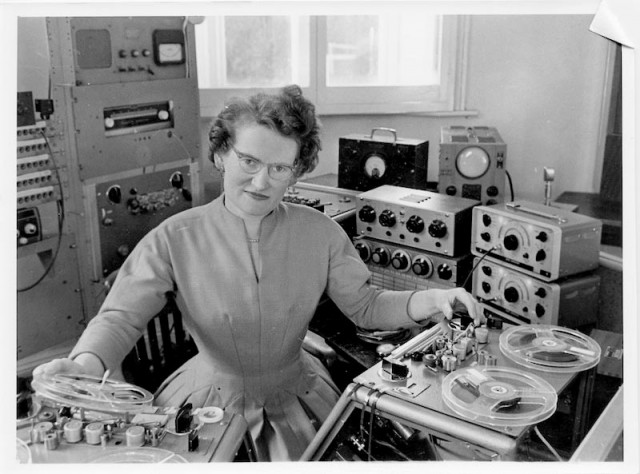
Oram worked at the BBC from 1942 to 1959 where she established the Radiophonic Workshop with Desmond Briscoe. She resigned from the BBC in 1959 to set up her own studio the ‘Oramics Studios for Electronic Composition’ in a converted oast-house in Wrotham, Kent. With the help of the engineer Graham Wrench, she built “with an extremely tight budget and a lot of inverted, lateral thinking” the photo-electrical equipment she christened ‘Oramics’ which she used to compose and record commercial music for not only radio and television but also theatre and short commercial films.1 Daphne Oram Website at: http://daphneoram.org
“There was an octagonal room,” remembers Graham, “where she’d set up her studio, but on a board covering a billiard table in an adjoining reception room was displayed the electronics for Oramics. There wasn’t very much of it! She had an oscilloscope and an oscillator that were both unusable, and a few other bits and pieces — some old GPO relays, I remember. Daphne didn’t seem to be very technical, but she explained that she wanted to build a new system for making electronic music: one that allowed the musician to become much more involved in the production of the sound. She knew about optical recording, as used for film projectors, and she wanted to be able to control her system by drawing directly onto strips of film. Daphne admitted the project had been started some years before, but no progress had been made in the last 12 months. I said I knew how to make it work, so she took me on. I left my job with the Medical Research Council and started as soon as I could.”2Steve Marshall, (2009),”Graham Wrench: The Story Of Daphne Oram’s Optical Synthesizer’ Sound on Sound magazine, february 2009.
Oramics Machine
The attraction of this technique was a direct relation of a graphic image to the audio signal and even though the system was monophonic, the flexibility of control over the nuances of sound production was unmatched in all but the most sophisticated analogue voltage controlled synthesisers. Daphne Oram continued to use the process throughout the sixties producing work for film and theatre including; “Rockets in Ursa Major”(1962), “Hamlet”(1963) and “Purple Dust” (1964).
Daphne Oram. Born Devizes, Wilts, 1925;Died Maidstone, Kent, 2003
References
1
Daphne Oram Website at: http://daphneoram.org
2
Steve Marshall, (2009),”Graham Wrench: The Story Of Daphne Oram’s Optical Synthesizer’ Sound on Sound magazine, february 2009.