‘Instrument de Musique Electronique’ – A diagram from Hugoniot’s patent for a tone-wheel sound generator, December 1919. Image: French Patent Office FR22866 – 05/09/1921.
Charles–Emile Hugoniot (died in France, 1927) was a French mechanic, researcher, and inventor of early electronic musical instruments. Hugoniot was awarded seven patents in France between 1919 and 1923 for various methods of sound generation, including tone wheels and photoelectric tone generators. Starting in 1919, Hugoniot began a process of improving existing sound generation devices of the period, first, Thaddeus Cahill’s electro-magnetic tone-wheels (from Cahill’s patents that would have been known to him in France) and continuing to electromagnetic steel discs and photo-electrical methods, possibly influenced by the South African physicist, Hendrik van der Bijl’s patents from 1916. By doing so, Hugoniot introduced these new methods to a French group of electronic engineers.
Hugoniot appears to have constructed only one instrument– a photoelectric organ described in his patent #FR550370 in 1921. The instrument was among the first to use a photoelectric technique to generate sound: Hugoniot projected a light beam onto a selenium photovoltaic cell through an array of 12 rotating discs, each cut with concentric rings of radial slits. The frequency (and speed of rotation) generated an electrical pulse from the photo-voltaic cell that equated to an octave pitch.
Hugoniot died in 1927 before he could develop his ideas beyond prototypes, yet he left a legacy of innovation that influenced a new generation of French pioneering instrument designers, including Pierre Toulon and Givelet & Coupleaux.1 Bush, D., & Kassel, R. (2004;2006;). The Organ: An Encyclopaedia, London: Taylor and Francis, 167.
Hugoniot’s patent for a photo-electrical sound generator, August 1921. Image French Patent Office FR550370D – 08/27/1921.
Benjamin Miessner, writing in the Proceedings of the Institute of Radio Engineers, USA 193,6 describes Hugoniot’s photo-electric sound generation ideas:
“With this scheme the various types of wave forms for different timbres may be placed in radial sectors on a disk; another disk carrying the scanning slits in circular tracks rotates before this wave-form disk. A source of light and photocell complete the translating arrangements. Each slit track scans its corresponding wave cycle at a speed corresponding to one pitch of an approximate tempered scale. Thus, one wave and one slit track serve for each tone frequency of the tempered scale. Naturally the lowest pitch tracks are nearest the center and the highest are nearest the circumference of the scanning disk.
Another interesting arrangement is that used by Lesti and Sammis in the Polytone. Here, instead of using a series of similar wave-form cycles on a continuous track, with a single scanning device, only one complete such cycle is used with periodic scanning by a series of similar scanning slits, equispaced on a continuous track. The slit spacing is precisely equal to the wave-form lengths, so that this wave form is repeated at the scanning frequency; i.e., the number of slits passing it per second. The same method was disclosed as early as 1921 by the French inventor Hugoniot, who described an electrical musical instrument of this type in his patent”.2 Miessner, Benjamin F, (1936) Electronic Music and Instruments, Proceedings of the Institute of Radio Engineers, New York, N.Y. Volume 24, November 1936, Number 11, 1427.
References
1
Bush, D., & Kassel, R. (2004;2006;). The Organ: An Encyclopaedia, London: Taylor and Francis, 167. ↩︎
2
Miessner, Benjamin F, (1936) Electronic Music and Instruments, Proceedings of the Institute of Radio Engineers, New York, N.Y. Volume 24, November 1936, Number 11, 1427. ↩︎
Rudolf Stelzhammer and Wilhelm Lenk demonstrating the Magenton at the Erfindermesse, London 1935
The Magneton, designed by Wilhelm Lenk at the University of Vienna, was a tone-wheel organ-like electronic instrument based on the same principles as Cahill’s Telharmonium (c1900) and the later Hammond Organ of Laurens Hammond and John Hanert; the electromagnetic principle of producing a voltage tone and associated timbres by spinning varied shaped metallic wheels within a magnetic field.
Tone-wheels of the Magneton arranged over 12 axles. Technology Museum Vienna.
The instrument’s contribution to tonewheel technology was to achieve a constant fixed rotation by using a frequency controlled motor regulator. This allowed the player to easily and accurately transpose the instruments switch at the flick of a switch.
Rudolf Stelzhammer and the Magenton in 1935
The first promotional model of the instrument was produced by the Vienna piano company Stelzhammer in 1930 – four years before the first Hammond organ hit the market. The instrument was designed as a practice instrument for ‘real’ pipe organs and as a way of encouraging active participation from the congregation in sacred music (as espoused by the “Popular Liturgy Movement” in pre-war Austria).
The Stelzhammer Magneton tone wheel organ, 1930.
“The slavish imitation of the sound of an organ and its characteristic rigidity was deliberately avoided, thereby giving the tone character of the instrument a number of special characteristics. What I like particularly in the magneton, 8 although I grew up with the pipe organ and have been inseparably associated with it for 50 years, is the fact that this new instrument is not an enemy of the historic organ.”
Vinzenz Gollerin the ‘Zeitschrift fur Instrumentenbau’ Vol. 54, 1933/34, p. 103
Despite a promising start, the Magneton failed commercially – only a few production models were built. A single surviving model can be found at the Vienna Museum of Technology, Austria.
Wilhelm Lenk
The Stelzhamer Piano shop at Barnabitengasse 1060 Wien.
Rudolf Stelzhammer. Biographical notes.
Rudolf Stelzhammer was born into a Viennese family of piano makers on the 03.11.1893. After learning the craft of piano construction and working in the family business he travelled throughout Europe and America working for large instrument manufacturers. Returning to Austria in 1924 he founded his own company in Vienna and from 1935 became the ‘guild master’ of the Austrian musical instrument producers. In 1966 Stelzhammer sold the business to the Ehrbar piano Company in Vienna. Stelzhammer was known for his scientific and electro-acoustic research which lead to several improvements in piano design. Stelzhammer was involved in the development of photoelectric experiments and was involved in the creation of the ‘Selenephon’ (1922) a device for printing optically recorded audio onto movie film. Rudolf Stelzhammer died in Vienna, Austria on 01.16.1967
Sources
Peter Donhauser, Elektrische Klangmaschinen. Die Pionierzeit in Deutschland und Österreich, 348 S., zahlr. s/w-Abb., Br., (Böhlau), Wien 2007. ISBN: 978-3-205-77593-5
The Organ: An Encyclopedia (Encyclopedia of Keyboard Instruments) by Douglas Bush, Richard Kassel (ISBN: 9780415941747)
S. Walter Fischer:. Technical In: L’Estrange Fawcett:. The world of film Amalthea-Verlag, Zurich, Leipzig, Vienna 1928, p 210-211
Franz Lechleitner: Selenophon. In: Oesterreichisches music lexicon. Online edition, Vienna 2002 ff. ISBN 3-7001-3077-5; Print Edition: Volume 4, Austrian Academy of Sciences, Vienna 2005, ISBN 3-7001-3046-5.
Melvin L. Severy was an American engineer and inventor from Arlington Heights, Massachusetts – probably best known as the inventor of the Choralcelo; a huge hybrid electronic and electro-mechanical organ and the culmination of many years research and experimentation with electro-acoustics1 See US patents US1098983, US1104282, US1137544, US1181486, US1190332, US1196401,US1201513, US1218324, US1245518, US1899884, US2155741. Severy was also responsible for numerous patents on inventions as diverse as typewriters (1903), bottling machines (1882), piano-tuning devices (1912), telegraphic systems, steam boilers (1893), steam engines (1894), cameras (1907), orthopaedic shoes, thermo-chemical batteries (1899), solar panels for generating electricity (1894), an iron-lung (1916) and what is probably the first audio ‘sampling’ instrument, which he described simply as ‘Sound Producing Device’ in 1912:2US Patent Office. Melvin L Severy US1218324 A. Publication date 6 Mar 1917
“The object of the present invention is the construction of an improved musical instrument in which the sonorous vibrations are produced electromagnetically by the movement of phonograms of magnetic material past electromagnetic sound producing mechanism.”3 M L Severy, Sound producing device, application filed mar, 22 1913. Patented mar 6, 1917 p1, part 10.
Diagram showing the key-action that moves the magnetic pick-up closer to the sound wheel. US1218324 A.2 March 1913.
It is unknown whether the ‘Sound-Producing Device’ was actually built – Severy didn’t use any similar mechanisms in the Choralcelo – yet the ‘Sound-Producing Device’ predicted the future of sampling instruments such as the Chamberlin and Mellotron by half a century and perhaps invented the concept of sampling.
Severy’s device was based around the concept of printing numerous magnetic spectrogram or recorded sounds as endless loops on rotating wheels. A magnetic pick-up would be placed near the spectrogram disk and in turn, transmit a variable magnetic pulse that would active a speaker membrane – or, in a manner similar to Cahill’s Telharmonium, transmit the signal through the newly established telephone network.
The instrument was to have numerous spectrogram for each note representing the various fundamentals and timbres of the recorded sound – a concept that was new for the time and most likely inspired by H. Helmholtz’s ‘On the Sensations of Tone as a Physiological Basis for the Theory of Music‘ (first published in English in 1875). These different timbres could be mixed using organ-style stops. Variation in pitch was achieved simply by altering the speed of the disc for each note and the volume of each note by keyboard pressure which moved the pick-up nearer to the sonogram disc.
Each note of the instrument had its own speaker making the ‘Sound-Producing Device’ fully polyphonic as well as velocity sensitive.
Severy suggested several possible formats for encoded spectrograms including a (fig 11) paper-roll strips for long recordings, (fig 14, 14) disks with multiple pick-ups and an Edison type tube (fig 13):
“There are many ways in which the timbre forms may be made, such as stamping them from thin sheet metal; printing them on the cylinder with a magnetic ink; printing them with a sticky ink and then dusting the impression with iron filings or other magnetic particles; by electroplating, or by using a coating of paste impregnated with magnetic filings and various other methods, as will be obvious. The main idea is to secure a uniform layer of magnetic material whose lateral extent varies according to the variations of the sound waves to be produced.” 4Melvin Severy. U.S. Patent notes. US1218324 A.2 March 1913
Severy had already, In 1910, patented an automatic spectrogram or ‘Harmonograms’ recorder that mechanical wrote a sound recording to a rotating disc that would allow the recording and production of spectrograms for his instrument:
Severy explained how the instrument could be used to record and playback any sound:
“It is evident that by having some fine singer deliver into a phonautograph one or more complete octaves of musical notes, singing the broad A, for instance, and then having these phonautographs reproduced into timbre forms the instrument can be adapted for the repetition of the tones of the human voice. It is only necessary to secure a phonautograph of a single octave of the original notes for the reason that the other tones required are the mere variable speed of the first.”5Melvin Severy. U.S. Patent notes. US1218324 A.2 March 1913
Melvin Linwood Severy. Biographical Notes.
Melvin Linwood Severy; born August 5, 1863 Melrose, Mass; died. Los Angeles, California 1951.
Severy was educated at Walpole, Mass. high school, Boston; grad school and Monroe Coll. of Oratory. Severy worked as a florist and as a teacher teaching elocution and oratory and as an actor (where he acted with Edwin Booth, brother of the assassin of Abraham Lincoln) Severy began his lengthy and successful career as an inventor in 1882 and eventually held over 80 patents including the Severy Printing Process (which won him John Scott medal of Franklin Institute in 1898), the Choralcelo, Vocalcelo and Vocalsevro (later name for the Choralcelo), fluid transmission for cars, telegraphic devices, engines, Health devices, typewriters and so-on.
Severy founded numerous businesses from his own inventions including the Ex-pres Severy Impression Process Co., Choralcelo Mfg. Co., Choralcelo Co., dir. Solar Power Co., and the Automatic Tympan Co.
As well as inventing, Severy found time to write books of fiction and non fiction including: ‘Fleur-de-lis and Other Stories’, ‘Materialization and Other Spiritual Phenomena from a Scientific Standpoint’ (1897), ‘The Darrow Enigma’( 1904), ‘ ‘The Mystery of June Thirteenth’ (1905), ‘Maitland’s Master Mystery’ and ‘Gillette’s Social Redemption (1907), ‘Gillette’s Industrial Solution’ (1903) both commissioned by King Gillette the inventor of the safety razor.
In ‘The Darrow Enigma’( 1904) Severy accurately predicts the use of light beams (lasers) as a surveillance method:
“The device whereby I secure this at such a distance is an invention of my own which, for patent reasons–I might almost say ‘patent patent reasons’–I will ask you to kindly keep to yourself. To the diaphragm there I fasten this bit of burnished silver. Upon this I concentrate a pencil of light which, when reflected, acts photographically upon a sensitised moving tape in this little box, and perfectly registers the minutest movement of the receiving diaphragm. How I develop, etch, and reproduce this record, and transform it into a record of the ordinary type, you will see in due time–and will kindly keep secret for the present.” 6 Severy, Melvin L. The Darrow Enigma, Project Gutenberg Australia, Chapter III.
Sources
1
See US patents US1098983, US1104282, US1137544, US1181486, US1190332, US1196401,US1201513, US1218324, US1245518, US1899884, US2155741 ↩︎
2
US Patent Office. Melvin L Severy US1218324 A. Publication date 6 Mar 1917 ↩︎
3
M L Severy, Sound producing device, application filed mar, 22 1913. Patented mar 6, 1917 p1, part 10. ↩︎
4
Melvin Severy. U.S. Patent notes. US1218324 A.2 March 1913 ↩︎
5
Melvin Severy. U.S. Patent notes. US1218324 A.2 March 1913 ↩︎
6
Severy, Melvin L. The Darrow Enigma, Project Gutenberg Australia, Chapter III. ↩︎
The Mastersonic Organ was an improved tone wheel organ designed to produce more accurate pipe organ sounds. The designers, John Goodell and Ellsworth Swedien, discovered that if they shaped the tone-wheel ‘pickups’ they could induce tones with different ‘natural’ harmonic content – rather than attempt to create a pure sine wave and artificially colour it as in the Hammond Organ. To achieve this the Mastersonic had individually shaped magnets for each tone wheel sound; a “string” magnet, a “flute” magnet, a “diapason” magnet, and so on.
Mastersonic Tone Generation (Alan Conway Ashton ‘electronics, Music and Computers’ 1971)
“…There were twelve shafts with seven pitch wheels each which rotated near the irregularly shaped magnets wound with coils. Each of the pitch wheels contained twice as many rectangular teeth as the preceding one, so seven octaves were produced per shaft. Several differently shaped poles were dispersed radially around each wheel.”
Alan Conway Ashton electronics, Music and Computers
Each tone-wheel was shielded against magnetic interference from the other, adding to the bulk and complexity of the instrument. The instrument was controlled by a seven octave special keyboard, designed to simulate attack envelopes. The resulting sound was indeed a much more accurate pipe organ sound but at the expense of size; the Mastersonic was a huge, complex and expensive machine and few were built or sold.
Sources
‘Microsound’ Curtis Roads MIT 2001
ELECTRONICS, MUSIC AND COMPUTERS. Alan Conway Ashton. December 1971 UTEC-CSc-71-117
The Robb Wave Organ, designed by Morse Robb in Belleville, Ontario, was an early precursor, and said to be musically superior, to the Hammond Organ. The instrument sought to reproduce the sound of a cathedral pipe organ by amplifying the output of a similar tone-wheel mechanism. Robb based his tone-wheel design on Melvin Severy’s Choralcelo, but added amplification, which wasn’t available to Severy at the time.
Frank Morse Robb. Image: (c) Notable Bellevillians https://www.mybelleville.net/single-post/2018/05/06/notable-bellevillians-gone-but-not-forgotten.
“…Such an instrument as his (Severy’s ‘Choralcelo’), however, is both practically and theoretically impossible, as without amplification, far greater than the microphone type he suggests, nothing but the faintest trace of tones could be heard. The mere addition of amplification to his instrument would not be an invention. If this were done, moreover, the instrument could not function musically, as the circuit and wiring arrangement set forth in his patent would preclude that possibility due to internal resistance in the magnets. Every impulse generated by the tone disc would be absorbed in the circuits to such an extent that amplification would be impossible.”
Morse Robb’s miniaturised tone wheels of the Wave Organ. From the collection of the Canada Science and Technology Museum, Ottawa, Ontario, Canada.
Robb’s aim was to miniaturise elements of earlier large-scale tone-wheel designs (Choralceloof 1909 and Telharmonium1897-1917) to create a practical, easy-to-maintain, and affordable electronic organ. This was achieved by reducing the size and number of the tone wheels, adding a gear system, and increasing the number of notes on each wheel by ‘doubling and redoubling the wave forms on the discs on one shaft’. The instrument was equipped with twelve tone wheels representing each note, the ‘character’ or timbre of note, corresponding to organ stops and photographed from a cathode ray oscillograph, plus the harmonics of each fundamental note. The variation in pitch of each note was achieved by changing the speed of the tone wheel’s rotation, giving the Wave Organ a total of five octaves. The tone wheels, spinning within a magnetic field, generated a voltage output for each note, which was made audible by being passed to a valve amplifier and a loudspeaker.
Significantly, the Wave Organ was unique in that it sought to replicate real organ sounds by cutting the tone wheels to the shape of a photographic image of a church organ’s waveform, rather than mechanically reproducing and combining ‘pure’ tones and overtones, as in the Telharmonium and Hammond Organ. In this way, the Wave organ can be seen as one of the earliest analogue sampling
The prototype Wave Organ was built in 1927, premiered in November of the same year at the Toronto Daily Star’s CFCA radio studio in Belleville, and was patented in 1928 (1930 in the USA). Robb planned to market the instrument by arranging a production contract with the General Electric Company in Schenectady, NY, and, later, with the organ builders Casavant Frères in Canada. The worsening economic conditions of the Great Depression permanently stalled the agreements in the spring of 1931. Undaunted by the commercial failure of his first prototype, Robb produced a new, two-manual, 32-note version of the Wave Organ in April 1934 and launched the ‘ Robb Wave Organ Company’- incorporated on 21 September 1934 – to market and sell the instrument. The first production models became available in July 1936 and were publicly demonstrated at Eaton’s department stores in Toronto and Montréal. Despite an initial positive reaction, Robb was unable to obtain funding for further production, and in 1938, he abandoned the project. Only 13 models were ever sold, and the Wave Organ was withdrawn from the market in 1941.1 Murphy, Michael and Cotter, Max, (2014) Frank Morse Robb’s Wave Organ, eContact! 17.3 — TIES 2014: The 8th Toronto International Electroacoustic Symposium.
The Robb Wave Organ was more expensive than other electronic organs of the period – notably the American Hammond Organ, which used an almost identical tone-wheel technology – and sales suffered because of World War II. The last remaining Wave Organ prototype is preserved at the Canada Science and Technology Museum in Ontario. 2 Murphy, Michael and Cotter, Max, (2014) Frank Morse Robb’s Wave Organ, eContact! 17.3, https://econtact.ca/17_3/murphy-cotter_robborgan.html retrieved 29/11/23
Second version of Morse Robb’s ‘Wave Organ’ c1936
Frank Morse Robb c1927. Image:
Frank Morse Robb
(born 28 January 1902 in Belleville, ON; died 5 August 1992 in Belleville)
Robb studied at McGill University from 1921 to 1924 and then returned to Belleville, where in 1926 began research on the Robb Wave Organ. After the commercial failure of the Wave Organ, Robb applied his inventing talent to devices for packing guns during the Second World War. He became vice president of his brother’s packing company and earned acclaim as a silversmith. He also wrote a Sci-Fi -post nuclear holocaust novel Tan Ming (1955) under the pseudonym Lan Stormont: “An amusing fantasy in which a department store window dresser falls in love with a robot mannequin and manages to conjure into its body the soul of a princess named Tan Ming from a postholocaust future.” 3 Morse Robb | The Canadian Encyclopedia”. thecanadianencyclopedia.ca. Retrieved September 11, 2019.
‘Tan Ming’ by Lan Stormont/Morse Robb 1955
References:
1
Murphy, Michael and Cotter, Max, (2014) Frank Morse Robb’s Wave Organ, eContact! 17.3 — TIES 2014: The 8th Toronto International Electroacoustic Symposium. ↩︎
2
Murphy, Michael and Cotter, Max, (2014) Frank Morse Robb’s Wave Organ, eContact! 17.3, https://econtact.ca/17_3/murphy-cotter_robborgan.html retrieved 29/11/23 ↩︎
3
Morse Robb | The Canadian Encyclopedia”. thecanadianencyclopedia.ca. Retrieved September 11, 2019. ↩︎
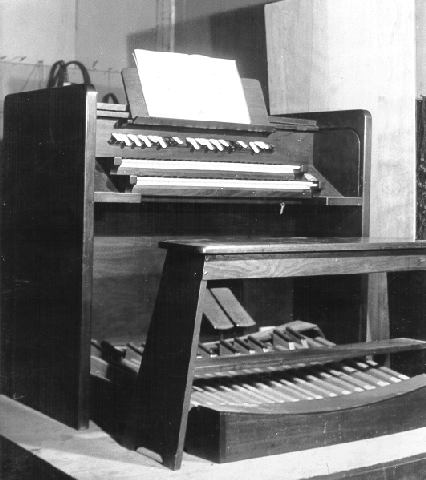
The keyboard manual of a Choralcelo installed in Denver Colorado. Photo Art Reblitz ca 1970.
The Choralcelo (“heavenly Voices” – pronounced: ‘Chor-al-Sello’) was a hybrid electronic and electro-acoustic instrument conceived as a high-end commercial domestic organ, aimed at wealthy owners of large country houses in the USA – houses large enough to accommodate the huge instrument. The Choralcelo was designed and developed by Melvin L. Severy with the assistance of his brother in law George B. Sinclair and manufactured by the ‘Choralcelo Manufacturing Co’ in Boston, Massachusetts. Later models were extensively redesigned and improved by Quincy Sewall Cabot, inventor of the ‘Synthetic Tone’.
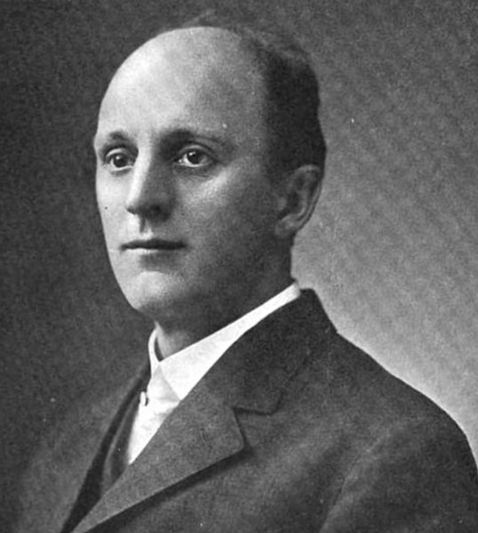
Melvin Severy b.1863 Melrose, Mass; d. California 1951
Severy was a prolific inventor (his patents included: printing presses, typewriters, solar heating systems, a camera, steam engines, fluid drives among many others) engineer musician, composer and author. The Choralcelo itself was a custom combination of the numerous electro-acoustic musical devices that Severy had designed since 1880 – electro-magnetic keyboard controls, tone generators and magnetic–acoustic string resonators 1“First Choralcelo Concert Proves Highly Successful,” The Musical Age (1 May 1909) . The first version of the Choralcelo was presented to the public on the 27th April 1909 at the Boston Symphony Hall, Boston, Mass accompanied by a soprano singer and forty members of the Boston Symphony Orchestra:
As for the Choralcelo itself, it proved an interesting and unique instrument. Fronting the audience from the platform was a mahogany box to disguise an upright piano somewhat exaggerated, and with two rows of keys. The Instrument, it was announced, resulted from twenty one years of persistent labour on the part of it’s inventor Melville (sic) L. Severy and George D. Sinclair both of Boston. The Choralcelo obtains sound of the violincello, the trumpet and the French horn , the oboe and the bassoon, the harp and the pipe organ from a single compass from the wire strings used in the pianoforte, which are vibrated by means of small electromagnets stationed at scientifically determined points along their length.
The surprise in the Choralcelo is that the ordinary piano string can be made to give more sounds than those obtained from it under the blows of the hammer, and the variety of these sounds is great on the account of the immensely increased possibility of making what the student musician knows as overtone. The concert this evening faithfully demonstrated the merits of the Choralcelo, and it may be expected to contribute important things to music. Great skill is required in it’s handling. The player is embarrassed somewhat by the very largeness of the means at his disposal. He must learn to select. With careful study this new instrument is designed to do many and large things and the contention of it’s inventor seems to be fully justified” 2 The Musical Age. New York, May 1st 1909.
programme of the first Choralcelo concert, Boston, 1909.
In 1915 The Choralcelo company was taken over by Wilbur Farrington and A. Hoffman (who, in some reports is named as its inventor). Sheets argues that by 1917 up to 100 of the instruments were produced 3Sheets, Arian, (2013) Choralcelo, Grove Music Online. Retrieved 27 Nov. 2021, from https://www.oxfordmusiconline.com/grovemusic/view/10.1093/gmo/9781561592630.001.0001/omo-9781561592630-e-1002240451. At least six of the instruments are known to have been sold4Jenkins, C.W (2002) The Choralcelo, Amica Bulletin. AMICA International
Automatic Musical Instrument Collectors’ Association and several continued to be used up unit the 1960’s – no working examples have survived.
The Choralcelo was a direct contemporary of the Telharmonium, though not quite as large, was still a huge instrument and, for the organ section of the instrument, used a similar electromagnetic tone-wheel sound generation method as the Telharmonium combined with a set of electromagnetically operated and sustained piano strings.
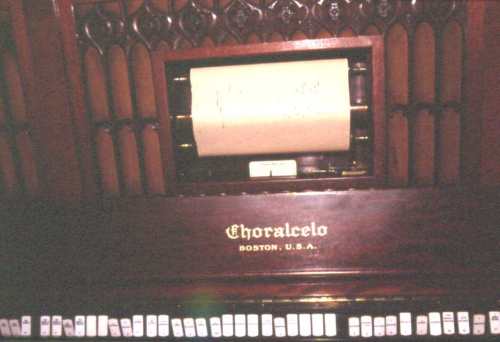
The visible part of the Choralcelo consisted of two keyboards, the upper (piano) keyboard having 64 keys and the lower 88 (piano and ‘organ’), controlling the invisible part of the instrument, usually in the basement of the house, consisting of 88 tone wheels and a set of piano strings and bells that were vibrated by electromagnets and a set of hammers. The keyboards also had a set of organ style stops to control the timbre and fundamentals of the tone that could then be passed through cardboard, hardwood, softwood, glass, steel or “bass-buggy” spring resonators to give the sound a particular tone.The Choralcelo also incorporated a pianola style paper roll mechanism for playing ‘pre-recorded’ music and a 32 note pedal board system. The entire machine could occupy two basements of a house, the keyboards and ‘loudspeakers’ being the only visible part of the instrument.
Sounds of the Choralcelo
“Poor Little Butterfly” from an original 78rpm glass master live 1942 recording, hand played by Regene Farrington, wife of Wilber Farrington, President of The Choralcelo Co. Recorded in the Choralcelo Studio in New York City. (from: C. W. Jenkins, AMICA)
Promotional brochure from the Choralcelo Manufacturing Co
Promotional material from the Choralcelo company
Detailed History of the Choralcelo from “History Of the Choralcelo” by W.Jenkins
“The information furnished is based on forty years of acquaintance with the instrument, and on three complete Choralcelo instruments at hand, friendship with one of the principals, interviews with others involved in the work, family members, original blueprints, all the patents issued, (and there were many) and original documents from the archives. “
“The story of the Choralcelo is largely the story of two men… Melvin L. Severy, born in 1863 in Melrose, Mass; died in California in 1951; and Wilber E. Farrington, born 1869, died 1945. Severy was a brilliantly gifted, multi-faceted inventor who secured patents on a printing press, solar heating, a camera, fluid drive, and many others, besides the Choralcelo. He was a scholar, artist, musical composer, and author. His grandson recalls that he was interested in secret passages in the pyramids, to name one of his many interests. Severy was assisted in his experimentation by his brother-in-law, George B. Sinclair. They had married Flint sisters. Wilber Farrington was an idealistic, philosophic visionary who devoted the majority of his life to his love of the unique tone of the novel instrument and his determination to see it successfully developed and manufactured. He was a charismatic and effective fundraiser and invested his own fortune in the work.There had been many efforts at strengthening or lengthening the tone of piano strings electrically.
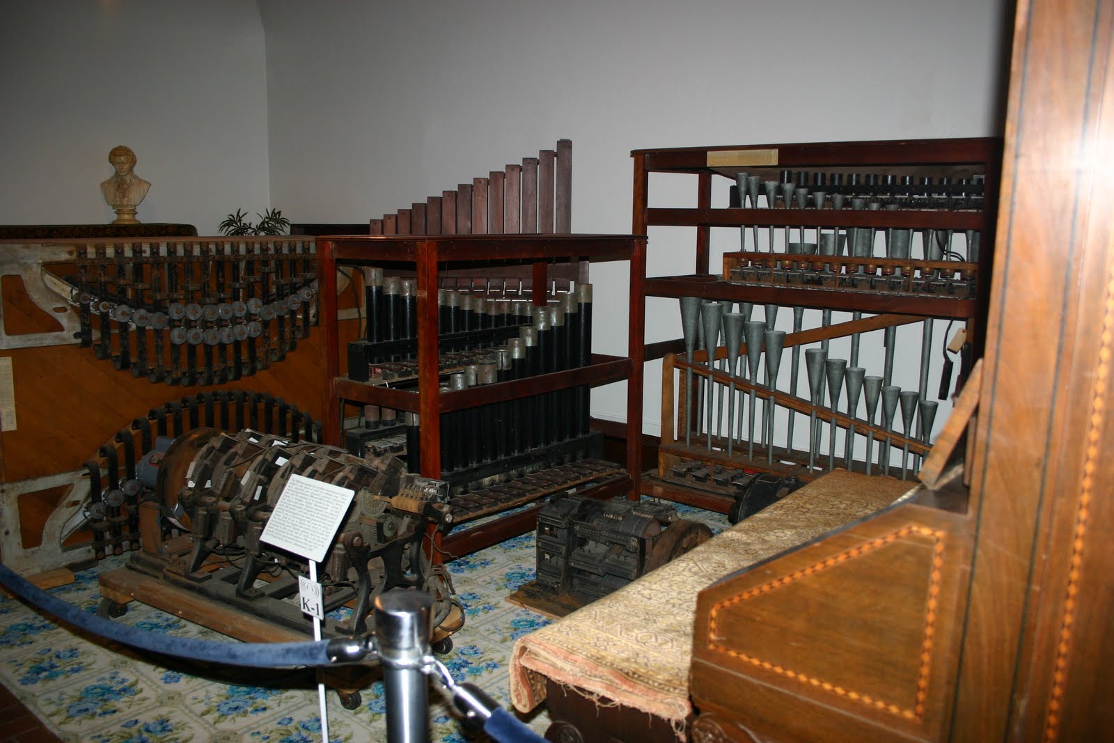
Remains of a Choralcelo at the National Music Museum, Vermilion Sands, South Dakota
As early as 1876, Elisha Gray had patented a single note oscillator; and in 1890 Eli C. Ohmart filed a patent on prolonging the tone of piano strings electromagnetically… the patent was assigned to Melvin Severy. The principle being worked on was simple… magnets were placed behind the strings of the piano, and accurately timed pulses of DC current were fed to the magnets coinciding with the natural periodicity of the strings.. for example, if note A vibrated at 440 vibrations per second, then 440 pulses of current per second would be fed to the magnets for that note, and sustained organ-like tone would be produced without the use of the hammers. The mechanism which accomplished this was the interruptor, powered by a small electric motor, which had nine brass cylinders 3 1/2″ long spinning at predetermined speeds. Each cylinder had eight make and break tracks 1/4 inch wide, alternate spaces being set in an enamel, a non-conductor. Sterling silver brushes rode on these tracks. The lowest notes required about 20 pulses per second, and the highest, about two thousand. The overwhelmingly difficult part was the governing of this device… the very slightest deviation and the frequency of the pulses would not coincide with the natural periodicity of the strings, and the tone will die. Patent after patent was filed for variations on governing mechanisms, some of them so elaborate that they were complicated mechanisms in themselves.
The basic concept of tone production, though simple, proved nearly impossible in execution… matching, on one side, an already tuned vibrating body, with perfectly matching pulses of magnetism, ranging anywhere from 20 vibrations per second to 2,000. The governing device controlling the speed of the make and break cylinders would not only have to provide such absolute perfection whenever called for, but would also have to be able to compensate for the vagaries of the electric current generated in that day, which powered the motor the drove the governor… to do this, it would have to be able to keep the cylinders rotating without the slightest deviation even if the motor driving the assembly slowed down or speeded up. If the speed of the cylinders changed while the instrument was being played, the tone would die out.
Remains of a Choralcelo at the National Music Museum, Vermilion Sands, South Dakota
An elegantly simple, brilliant magnetic combination governor and clutch evolved, which performed perfectly without physical contact, so there could be no overheating, and there were no clutch pads or other friction assemblies to wear out. Even today it is a marvel of brilliant application of principles of physics , and a marvel at least to those who are aware of what they are seeing to watch the spinning copper band drive the heavy flywheel merely by cutting through the invisible magnetic force. It is so disarmingly simple one could have no inkling of the years of labor which preceded it. Appreciating what it represents, I still have a feeling of awe. I doubt there has ever been anything like it, before or since. It was through the many mechanisms Severy laboured over and patented in his determination to solve the problem that fluid drive evolved. The first concert was given in 1905, and was by invitation.
The Choralcelo of that first phase of development was an impressive upright piano with one keyboard, usually with a roll player; the case of the finest grain mahogany with beautifully hand-carved openwork scroll panels. The tone could be varied by means of a slider near the left hand. It was the first tone produced without physical contact of some kind, and the tones produced invoked orchestral instruments minus the sound of the bow on the string or the breath of the flutist.
Development continued and a two manual instrument marked the second level, or phase, of the evolution of the Choralcelo. It still had the piano keyboard and piano strings which were excited by magnets. The piano strings were tuned by means of screws to attain greater stability. There was an organ keyboard above the first one, and a row of stops to control the range of tone units. These took the form of sets of tuned bars, or plates, which could be of steel, or wood, or aluminium, or sometimes glass. There were usually 41 to a set, and typically they varied in length from 5 3/4″ to 10 1/2″, and usually were about 5/16″ thick. Materials other than steel had small iron armatures affixed so that there would be response to the magnets.
Installed directly over these bars were resonating chambers, usually cylindrical fiber tubes, open at each end, which reinforced the tone, just as one sees in marimbas and vibraharps, The tone production was entirely acoustic; there was nothing electronic about the Choralcelo… no amplifiers, no loud speakers, no tubes… nothing of the sort. These sets of bars were remote from the main console and could be placed anywhere. The switching and control devices were remote from the main console and could be contained in two cabinets, each about 5 1/2′ high, and installed in the basement, along with the interrupter mechanism and motor-generator which delivered 30 volts of DC. The bar units could also be installed in the basement if desired, in which case grillwork was installed in the floor above them to transmit the sound; or they could be installed in the music room where the console was and concealed behind panelling or whatever was desired. The units were all connected by cables, usually armored with interwoven wire strands to protect them from damage. If all the machinery and also the bar units were to be placed in the basement, the space required would be approximately that of a modest bedroom.
Melvin L Severy circa 1915
The final phase of the development of the Choralcelo was the rewiring of the controls so that upper partials could be at the command of the Choralcelist and thus the potential of the instrument was greatly expanded because infinite variations and combinations were now available. The attempt to produce a completely new, unique instrument of this complexity in such a short period of time… the original factory closed in 1917 because of the war… was a monumental undertaking, and the multiplicity of the directions one might take was daunting. After all, the piano metamorphosed over several centuries, and other instruments have done the same. Experiments were conducted with reeds. A magnificent, large double bass unit having steel ribbons instead of individual strings was developed… there was a remote full-sized string unit which could be remotely placed… A variation of the interrupter mechanism was developed using brass discs instead of the earlier cylinders. There were twelve discs, each with six tracks, rotating at speeds determined by the gearing. All of these inventions, some of which were superseded by later ones, required designing, engineering, machining.. the investment was astronomical. In today’s money it amounted to many hundreds of millions of dollars. The instruments themselves were expensive, by today’s standards costing about a half million.
There were about one hundred built, many of them being installed in the music rooms of the wealthy. There were some that were in theatres to accompany silent films… Filene’s in Boston had two, one in the restaurant. Lord and Taylor in New York, and Marshall Field in Chicago, among others, featured Choralcelos, as did several hotels. There were even two on yachts.
The effort was a daunting task but great strides had been made by the time WWI broke out… materials were no longer available and as a result, the factory closed. Farrington and several of the most devoted men involved remained active in several locations, Cleveland, Chicago, Port Chester, Connecticut, and New York among them. The last activity was a demonstration studio in New York City, but another world war broke out and the studio closed in 1942.”
Choralcelo Patent Files
Choralcelo patent files
‘The Choralcelo, a Wonderful Electric Piano’
‘The Electrical Experimenter’ Magazine, USA. March 1916
This Marvelous Electrically Operated and Controlled Musical Instrument is More Than a Piano – It Produces Sustained Notes of the Lowest and Highest Register, Over a Range Heretofore Unattainable, and, Moreover, is Played Like a Regular Piano
In India, far away, as the popular song goes, the natives are content to regale themselves musically with plaintiff notes given forth by a goat skin stretched over the end of a hollowed log, upon which the musician beats a tune with the flat of his hand.
The music of the caveman was the wind is sighing through the trees, accompanied by the rustle of the leaves. Even they wanted to express themselves in a harmonious manner, hence the drum, the horn and other crude instruments of musical expression.
Then we may possibly expect some marked advances in our musical culture and education since the advent of the “Choralcelo,” despite the prophecies of those who take a pessimistic view of life in general.
The piano becomes a tongue-tied infant beside the latest masterpiece of the musician’s art. At times its notes thunder forth and seem to shake the very earth itself, and then again they may be subdued to an elusive softness like unto the faint notes of a distant church choir.
But what is it? How is it accomplished? What is the result of many years of untiring labor on the part of several of the cleverest men of the world? What is it upon which a fortune that would ransom a king has been spent? The Choralcelo!
The Choralcelo, the most wonderful musical instrument ever thought out by the human mind, is like nothing else the world of music has ever known. This masterpiece reproduces any piece of music in any form of instrument, from a string to a flute; not only does it reproduce them, but the notes emitted by it are sustained, pure and sweet, which is entirely different from the ones produced by the instruments that are in present use.
Practically all the musical instruments, previous to the invention of the Choralcelo, carry into the tone which they produce certain impurities which arise from the manner in which they are caused to vibrate. The violin interrupts the free vibration of the string by the grating rub of the bow. The piano adds the noise that results from the blow of the hammer on the string – while the organ mingles the breathiness of its air current with the pure vibrations of the column of air in the pipe. In like manner all instruments employing extraneous contacts to start the vibration destroy the purity of the note produced. And as they seek to amplify the tone they have produced they increase the intrusion and false sounds. The soft pedal of the piano, the swell-box of the organ, the mute of the violin, are just so many outrages on the purity of the tone.
The Choralcelo, by the very means which it employs in producing the tones, is freed from all obstructions. Vibration without contact, involving perfect freedom of vibration, and thus the Choralcelo gives all the natural overtones and harmonics; rich – full – pure and perfect, thus opening to the musician wonderful possibilities of expression and emotional power of which he possibly never dreamed.
The manner in which this result is accomplished is one of wonder. It is the subtle pull of the electromagnet which now achieves pure tone production. These electromagnets are caused to act directly upon the strings of the instrument.
The most delicate graduation of tone power can be produced by the mere variation of the strength of an electric current, and not by smothering devices which the present form of instrument employs. The tone, therefore, retains all its original purity through all vibrations and intensity, something that has been impossible heretofore.
We will next inspect the mechanism employed to perform these wonders. It may be stated that the vibrating elements are caused to oscillate by means of a pulsating electric current sent through an electromagnet acting on the vibrating membrane.
The machine which beaks up continually the electric current into a series of waves is really the “heart” of the Choralcelo. The operating device consists essentially of a series of metal discs having a certain number of insulating segments inserted into their peripheries. These discs are arranged to revolve at a fixed speed. Silver-tipped brushes are so placed that they will bear upon the revolving discs. It will thus be seen that in order to produce the fundamental periodicity of any given “string”, it is only necessary to rotate a disc containing a certain number of segments at the correct speed.
A large number of combinations are possible through the manipulation of a few keys, which correspond to the stops of an organ, and such a keyboard is clearly shown at Fig. 1. This resembles a piano, and it really is one, with additional keys and pedals. The pedals are used to vary the strength of the current sent through the electro-magnets.
A tremolo effect is given by means of a slow speed interrupter giving a pulsating current at a few revolutions per second. The instrument which produces this effect is depicted on the right of Fig. 2, while the one towards the left reproduces tones representing a flute. The regulation piano tone is produced with the usual percussion hammers, which may be thrown into or out of action by the pressure of a key. The staccato notes of the piano may be struck upon strings already vibrating with the pulsating current. Thus sustained notes of a higher pitch are produced upon the string.
A piano which employs both the electro-magnets and hammers is clearly shown on the left of Fig. 3. Note the large number of wires which are employed for connecting the various for connecting the various magnet coils. It is an engineering feat in itself to even make and wire the various circuits.
Marvelously sweet tones are produced by vibrating pieces of brass, wood and aluminum. In fact, any resonant body susceptible to vibration may be made to emit tones. In order to cause these bodies to vibrate, it is necessary to place within them a small piece of iron, so that the electro-magnets may attract them. Instruments that are operated by this method are depicted in Fig. 3. The one toward the right is an instrument that imitates a flute. The electro-magnets are placed underneath the tubes, which are made out of wood and act as resonating chambers. The magnets are caused to act on iron discs mounted at the lower end of the tube. Another style of flute instrument is illustrated in Fig. 4. This employs a different variety of tubes, ranging from a very high tone to a very low one. The smaller pipes give the latter tone, while the larger ones the former.
The instrument shown in the center of Fig. 3 illustrates a brass chime. The tones are produced by hammers, each of the tubes being supplied by one. These are operated by electro-magnets, as perceived in the upper bracket of the stand. These are also connected to the same keyboard.
The very deep tones of an organ are produced by vibrating diaphragms placed beneath metal horns. A pair of electromagnets are held a minute distance away from the diaphragm and serve to vibrate the latter when the pulsating current is applied. The volume of the tones is powerful and is very pleasant although it is very low. By increasing the power in the electro-magnets, the strength of the tones is so much increased that it is almost impossible to imagine the effect.
“Echo” combinations may also be installed without limit wherever their effect may be most beautiful at any distance from the master instrument. Thus the greatest cathedral may be filled with a glory of sound. The tower may be used to flood the surrounding country with the same divine melody. It may also be carried to the quiet cloister and to the private room. An instrument played in one place may repeat its music elsewhere.
The Choralcelo was developed and its wonderful basic principle discovered by Melvin L. Severy of Arlington, Mass., and George B. Sinclair. These savants have been working for twelve years to bring this musical instrument up to the perfection which it has reached today. One cannot predict its possibilities or limits as it is really still in its early stages of development. 5‘The Choralcelo, a Wonderful Electric Piano’
‘The Electrical Experimenter’ Magazine, USA. March 1916
Sources
1
“First Choralcelo Concert Proves Highly Successful,” The Musical Age (1 May 1909) ↩︎
Sheets, Arian, (2013) Choralcelo, Grove Music Online. Retrieved 27 Nov. 2021, from https://www.oxfordmusiconline.com/grovemusic/view/10.1093/gmo/9781561592630.001.0001/omo-9781561592630-e-1002240451. ↩︎
4
Jenkins, C.W (2002) The Choralcelo, Amica Bulletin. AMICA International
Automatic Musical Instrument Collectors’ Association ↩︎
5
‘The Choralcelo, a Wonderful Electric Piano’
‘The Electrical Experimenter’ Magazine, USA. March 1916 ↩︎
H.Trabandt: ‘Das Choralcelo’ ZI,xxix (1910)-‘Das Choralcelo als Konzertinstrument’ ZI xxx (1910)
The Rangertone Organ was a large electronic tone-wheel based organ developed by the electronics engineer and pioneer of audio recording Richard Ranger in the 1930’s. The instrument was marketed by Ranger from his own company ‘Rangertone Incorporated’ on Verona Ave. in Newark, NJ. Very few of the instruments were sold, one of which was installed at the Recital hall of Skinner Hall of Music, Vassar College. After the failure to sell the instrument Ranger went on to develop a series of high fidelity phonograph devices that never went into production. During WW2 Ranger spent time investigating German electronic equipment for the US Army and it was here that he picked up and removed for his own use the German AEG Magnetophone tape recorder. Ranger returned to the U.S. and in 1947 announced his new Rangertone Tape recorder, based on the Magnetophone, which finally gave the Rangertone Inc the financial success it needed until squeezed out of the domestic market by larger companies such as Ampex.
Richard Ranger with the wireless facsimile system. in 1924, Richard Ranger invented the wireless photoradiogram, or transoceanic radio facsimile, the forerunner of today’s fax machines. A photograph of President Calvin Coolidge sent from New York to London in November 1924 became the first photo picture reproduced by transoceanic radio facsimile.
The Rangertone Organ was one of the early tone wheel organs, similar to the Hammond Organ and much earlier Telharmonium (1906). Uniquely, the Rangertone Organ had its pitch stability controlled by tuning forks, therefore it was possible to change the temperament by changing the tuning of the forks. Timbre was controlled by push-buttons to the right of the keyboard, and/or by switching between six different amplifier/speaker combinations, which had different tremolo and tonal qualities.The original version was a huge machine, with more than 150 valves. A portable single-keyboard model was built for concert performance.1
Ranger made the first public demonstration of his huge ‘pipeless organ’ at Newark, New Jersey in 1931:
Interior of the Rangertone organ. Image: Proceedings of the institute of Radio Engineers November 1936 Volume 24, Number 11, 1444.
“Ranger’s apparatus consisted essentially of twelve separate sets of motor-driven alternators precisely maintained at given rotational speeds, by tuning-fork control apparatus. One of these sets of alternators, as shown in Fig. 5, generated all the required C’s; another all the C sharps; another the D’s, and so forth. From these alternators he obtained all the desired fundamentals and their true harmonic frequencies for the tempered scale. Timbre control switches selected the partials and their amplitudes for any desired tone quality. Amplifiers were, of course, used with reproducers to translate the feeble audio currents into sound.
Ranger’s improvements over the basic work of Cahill were made possible by the advent of the vacuum tube. For example, he provides means for automatic selection of different amplifiers, for different simultaneously produced tones, to prevent cross modulation in a single amplifier; means for avoiding keying transients, for accentuating high or low frequencies, for restricting tremolo to specific components of a complex tone, and at different tremolo rates, means to provide glissando effects, for regulating the temperament, for providing damped wave trains in simulation of percussive tones, and numerous other details.” 1 Meissner, Benjamin. F,(1936) Electronic music and instruments, Proceedings of the institute of Radio Engineers November 1936 Volume 24, Number 11, 1444.
Ranger, Richard Howard – Inventor, USA *13.06.1889-10.01.1962+ with the Rangertone Organ 1930 – Image: Sennecke Vintage property of ullstein bild (Photo by Robert Sennecke/ullstein bild via Getty Images)
Interior of the Rangertone organ. Image: Proceedings of the institute of Radio Engineers November 1936 Volume 24, Number 11, 1444.
“Ranger’s apparatus consisted essentially of twelve separate sets of motor-driven alternators precisely maintained at given rotational speeds, by tuning-fork control apparatus. One of these sets of alternators, as shown in Fig. 5, generated all the required C’s; another all the C sharps; another the D’s, and so forth. From these alternators he obtained all the desired fundamentals and their true harmonic frequencies for the tempered scale. Timbre control switches selected the partials and their amplitudes for any desired tone quality. Amplifiers were, of course, used with reproducers to translate the feeble audio currents into sound.
Ranger’s improvements over the basic work of Cahill were made possible by the advent of the vacuum tube. For example, he provides means for automatic selection of different amplifiers, for different simultaneously produced tones, to prevent cross modulation in a single amplifier; means for avoiding keying transients, for accentuating high or low frequencies, for restricting tremolo to specific components of a complex tone, and at different tremolo rates, means to provide glissando effects, for regulating the temperament, for providing damped wave trains in simulation of percussive tones, and numerous other details.” 1 Meissner, Benjamin. F,(1936) Electronic music and instruments, Proceedings of the institute of Radio Engineers November 1936 Volume 24, Number 11, 1444. ↩︎
The original Hammond Organ was Designed and built by the ex-watchmaker Laurens Hammond and John M Hanert in April 1935. Hammond set up his ‘Hammond Organ Company’ in Evanston, Illinois to produce electronic organs for the ‘leisure market’ and in doing so created one of the most popular and enduring electronic instruments ever built.
Hammond’s machine was designed using technology that relates directly to Cahill’s ‘Telharmonium’ of 1900, but, on a much smaller scale. The Hammond organ generated sounds in the same way as the Telharmonium, the tone wheel – The tone generator assembly consisted of an AC synchronous motor connected to a gear train which drove a series of tone wheels, each of which rotated adjacent to a magnet and coil assembly. The number of bumps on each wheel in combination with the rotational speed determined the pitch produced by a particular tone wheel assembly. The pitches approximate even-tempered tuning.
This method of creating tones was maintained until the mid 1960’s when transistors replaced tone wheels
The Hammond had a unique drawbar system of additive timbre synthesis (again a development of the Telharmonium) and stable intonation – a perennial problem with electronic instruments of the time. A note on the organ consisted of the fundamental and a number of harmonics, or multiples of that frequency. In the Hammond organ, the fundamental and up to eight harmonics were available and were controlled by means of drawbars and preset keys or buttons.A Hammond console organ included two 61-key manuals; the lower, or Great, and upper, or Swell, and a pedal board consisting of 25 keys. The concert models had a 32-key pedalboard. Hammond also patented an electromechanical reverb device using the helical torsion of a coiled spring, widely copied in later electronic instruments.
As well as being a successful home entertainment instrument, The Hammond Organ became popular with Jazz, Blues and Rock musicians up until the late 1970’s and was also used by ‘serious’ musicians such as Karlheinz Stockhausen in “Mikrophonie II”